The
graphic files in this document have been saved as "thumbnails" to
facilitate downloading of the document. "Click" on the small
image to expand it in a new browser window. It is suggested that you print
the figure from that new window.
All
figures can be accessed from this list: Fig.2.1, Fig.2.2,
Fig.2.3, Fig.2.4, Fig.2.5,
Fig.2.6, Fig.2.7, Fig.2.8,
Fig.3.1, Fig.6.1, Fig.6.2,
Fig.8.1, Fig.8.2 and Fig.8.3
Preface
The preparation of the Scientific and Technical Guidelines of the Commission
on the Limits of the Continental Shelf was conducted in two stages. The
first stage consisted of background research conducted along disciplinary and
interdisciplinary lines. The Commission organized six research groups for
this purpose, established at its second session in September 1997:
(a) Hydrography (Srinivasan, Chairman;
Albuquerque, Astiz, Awosika, Carrera, Francis and Lamont, with Rio as an
alternate);
(b) Geodesy (Carrera, Chairman;
Albuquerque, Astiz, Brekke, Francis, Hamuro, Jaafar, Mdala and Srinivasan,
with Rio as an alternate);
(c) Geology (Park, Chairman; Betah,
Brekke, Hamuro, Juracic, Kazmin, Lu, Mdala and Srinivasan, with Carrera as an
alternate);
(d) Geophysics (Croker, Chairman;
Awosika, Carrera, Hinz, Lu, Mdala and Park, with Francis as an alternate);
(e) Foot of the continental slope (Rio,
Chairman; Carrera, Francis, Hamuro, Kazmin, Lamont and Srinivasan);
(f) Outer edge of the continental
margin (Brekke, Chairman; Albuquerque, Astiz, Betah, Carrera, Croker, Hamuro,
Juracic, Kazmin, Lu, Mdala and Park).
The second stage consisted of the preparation of draft Guidelines, which
began at the third session of the Commission, held at United Nations
Headquarters in New York from 4 to 15 May 1998. An Editorial Committee was
established at the session and Galo Carrera was elected as its Chairman.
The Editorial Committee considered and adopted the document structure for the
Guidelines proposed by its Chairman.
The Editorial Committee was organized into 13 working groups, whose Chairmen
reported to the Chairman of the Editorial Committee, as follows:
(2) Entitlement to and delineation of
the outer limits of the continental shelf (Carrera, Chairman; Albuquerque,
Brekke, Hamuro, Hinz, Lamont and Rio);
(3) Geodetic methodologies and the
outer limits of the continental shelf (Carrera, Chairman; Albuquerque, Astiz,
Francis, Hamuro, Jaafar, Mdala, Rio and Srinivasan);
(4) The 2,500 metre isobath (Lamont,
Chairman; Albuquerque, Astiz, Awosika, Carrera, Francis, Hinz, Kazmin, Rio and
Srinivasan);
(5) Foot of the continental slope
determined as the point of maximum change in the gradient at its base (Rio,
Chairman; Albuquerque, Astiz, Carrera, Croker, Francis, Hamuro, Kazmin and
Lamont);
(6) Foot of the continental slope
determined by means of evidence to the contrary (Hinz, Chairman; Betah,
Brekke, Carrera, Jaafar, Juracic, Kazmin and Park);
(7) Ridges (Hamuro, Chairman; Brekke,
Hinz, Juracic, Kazmin, Lu and Park);
(8) Delineation of the outer limits of
the continental shelf based on sediment thickness (Brekke, Chairman; Awosika,
Croker, Juracic and Park);
(9) Information on the outer limits of
the extended continental shelf (Albuquerque, Chairman; Brekke, Carrera, Hamuro,
Hinz, Lamont and Rio);
(10) References and bibliography
(Carrera, Chairman; Editorial Committee);
(11) List of international
organizations (Carrera, Chairman; Editorial Committee);
(12) Flowcharts, tables and
illustrations summarizing the procedure for establishing the outer limits of
the continental shelf (Jaafar, Chairman; Carrera, Chan Chim Yuk,
Juracic, Lamont, Rio);
(13) Oversight (Awosika, Chairman;
Astiz, Beltagy, Betah, Chan Chim Yuk and Hamuro).
The Editorial Committee assigned to the first 12 working groups the task of
preparing 10 chapters and 2 annexes. The Oversight Working Group was
entrusted with two assignments: it was first asked to identify the
totality of issues raised in the studies prepared by the Division for Ocean
Affairs and the Law of the Sea on the basis of discussions held during two
meetings of groups of experts in 1993 and 1995. Secondly, it was requested
to determine whether those issues were addressed in the Guidelines. The 12
drafting groups produced a preliminary outline draft of the Guidelines, which
was discussed during the last plenary meeting of the Editorial Committee held
during the third session of the Commission.
All working groups conducted their main drafting efforts during the
inter-session period of 1998. On 20 July 1998, the revised version of the
draft Guidelines was submitted to the Chairman of the Editorial Committee, who
proceeded to edit them for consistency in content and style.
The Editorial Committee reconvened at the fourth session of the Commission,
held at United Nations Headquarters from 31 August to 4 September 1998.
The draft of the Guidelines edited by the Chairman of the Editorial Committee
was discussed at various plenary meetings of the Editorial Committee, where
amendments and clarifications were introduced in an iterative revision process.
The oversight group then proceeded to prepare and submit an interim report based
on the final draft produced by the Editorial Committee at that session.
The Chairman of the Editorial Committee submitted the final draft Guidelines
to the Commission at large for consideration during the last meeting of its
fourth session. The Commission, in turn, considered them and agreed to
adopt them provisionally. The Commission also agreed to make them
available to States on 4 September 1998 as a document in the "L"
(limited distribution) series.
The Commission worked during the inter-session period 1998-1999 with a view
to considering the recommendations made in the interim report prepared by the
Oversight Working Group at its 4th meeting. The members of the Commission
also considered other issues on which consensus was not reached, which were left
open for further discussion at its 5th meeting. Editorial comments on the
English text of the Guidelines were produced during this inter-session period by
Albuquerque, Astiz, Brekke, Carrera, Chan Chim Yuk, Croker, Lamont, Lu and
Srinivasan.
The following members revised the translation of the Guidelines from English
into other official languages of the United Nations: Arabic translation (Beltagy);
Chinese translation (Lu); French translation (Albuquerque, Betah, Chan Chim Yuk
and Rio); Russian translation (Kazmin); and Spanish translation (Albuquerque,
Astiz and Carrera).
The Guidelines were discussed and amended at the fifth session of the
Commission and adopted on 13 May 1999.
The drafting of the Scientific and Technical Guidelines of the Commission on
the Limits of the Continental Shelf during a relatively short period of time
represents an important achievement towards the implementation of article 76 of
the United Nations Convention on the Law of the Sea.
The Guidelines, which the Commission adopted by consensus, serve multiple
purposes: they are primarily intended to assist coastal States in
preparing their submissions. They are also designed to provide an
important scientific and technical reference for the consideration of these
submissions and the preparation of the Commission's own recommendations.
And last but not least, they form the basis on which the Commission shall
provide advice, if requested by coastal States during the preparation of their
necessary data.
The members of the Commission have an obligation to perform their duties
honourably, faithfully, impartially and conscientiously. These principles,
which form the essence of their solemn declaration, have guided them in the
preparation of their Scientific and Technical Guidelines.
The Commission expresses its gratitude to the Division for Ocean Affairs and
the Law of the Sea under the leadership of Mr. Ismat Steiner, Director.
Special thanks goes to the Secretary of the Commission, Mr. Alexei Zinchenko,
and to Lynette Cunningham, Vladimir Jares, Cynthia Hardeman and Josefa Velasco,
who ably assisted in the preparation of the Guidelines and in their expedient
publication.
1.1. The Commission on the Limits of the
Continental Shelf recognizes the integral character of the United Nations
Convention on the Law of the Sea (the Convention). These Scientific and
Technical Guidelines form the basis for the Commission to make its
recommendations with respect to submissions prepared by States according to
article 76 and Annex II to the Convention in a manner that is consistent with
the Convention and international law.
1.2. The Commission prepared these Guidelines
for the purpose of providing direction to coastal States which intend to submit
data and other material concerning the outer limits of the continental shelf in
areas where those limits extend beyond 200 nautical miles from the baselines
from which the breadth of the territorial sea is measured. The Guidelines
aim to clarify the scope and depth of admissible scientific and technical
evidence to be examined by the Commission during its consideration of each
submission for the purpose of making recommendations.
1.3. With these Guidelines, the Commission aims
also to clarify its interpretation of scientific, technical and legal terms
contained in the Convention. Clarification is required in particular
because the Convention makes use of scientific terms in a legal context which at
times departs significantly from accepted scientific definitions and
terminology. In other cases, clarification is required because various
terms in the Convention might be left open to several possible and equally
acceptable interpretations. It is also possible that it may not have been
felt necessary at the time of the Third United Nations Conference on the Law of
the Sea to determine the precise definition of various scientific and technical
terms. In still other cases, the need for clarification arises as a result
of the complexity of several provisions and the potential scientific and
technical difficulties which might be encountered by States in making a single
and unequivocal interpretation of each of them.
1.4. The Commission designed these Guidelines
with a view to ensuring a uniform and extended State practice during the
preparation of scientific and technical evidence submitted by coastal States.
The Commission is aware that there might be other scientific and technical
methodologies used by States to implement the provisions of article 76 to
prepare a submission which may not be covered in this document. These
Guidelines are not intended to exhaust the full range of possible methodologies
contemplated by States. Whereas several scientific and technical avenues
are available to develop an admissible body of evidence which may conform
equally to all the relevant provisions contained in the Convention, the
Commission has endeavoured to emphasize those which might minimize costs and
result in the optimization of existing information and resources.
1.5. The scientific nature and the order of the
paragraphs in article 76 define the structure of the Guidelines. Each
chapter starts with a formulation of the problem posed by each of its
provisions, followed by an in-depth discussion of its implementation.
Chapter 2 presents an overview of questions relating to the entitlement to an
extended continental shelf and the delineation of its outer limits.
Chapter 3 reviews units of length and describes the geodetic methodology used to
determine outer limits based on metrics. Chapter 4 describes the
hydrographic methodology used to determine the 2,500 metre isobath and other
geomorphologic features. Chapter 5 discusses the determination of the
location of the foot of the continental slope as the point of maximum change in
gradient at its base. Chapter 6 examines the case in which evidence to the
contrary might be presented as an alternative to the methodology described in
chapter 5 to determine the location of the foot of the continental slope.
Chapter 7 discusses the classification and treatment of oceanic and submarine
ridges, and other submarine elevations. Chapter 8 discusses the
geophysical methodology applied for the determination of sediment thickness and
its error estimates. Chapter 9 describes the data and other material to be
included in a submission regarding the outer limits of the continental shelf.
1.6. The Commission recognizes that the
Convention poses in-depth requirements in several scientific disciplines and
also poses the need for interdisciplinary scientific and technical cooperation
for the preparation of data and materials in each submission. These
Guidelines are not aimed at describing in detail the scientific theories or
precise technical methodologies involved in each discipline. For that
purpose, experts assigned to the preparation of submissions are advised to
consult the contributions made by many scientific and technical, governmental
and non-governmental organizations and disseminated through journals, conference
proceedings and other publications.
1.7. The annex provides a non-exhaustive list
of international scientific and technical organizations whose data and
information might be of interest to States which intend to prepare a submission.
Whereas those international organizations have the primary responsibility to
promote the development of knowledge and research in their respective
disciplines, the Commission has the sole responsibility to make recommendations
and to provide scientific and technical advice in relation to submissions on the
limits of extended continental shelves made by coastal States according to
article 76 and Annex II to the United Nations Convention on the Law of the Sea.
2. Entitlement to an extended
continental shelf and the delineation of its outer limits
2.1. Formulation of the problem: article 76
2.2. Test of appurtenance
2.3. Delineation of the outer limits of the continental
shelf
2.1.1. Article 76, paragraph 1, establishes the right of coastal
States to determine the outer limits of the continental shelf by means of two
criteria based on either natural prolongation or distance:
"The continental shelf of a coastal State comprises the sea-bed and
subsoil of the submarine areas that extend beyond its territorial sea
throughout the natural prolongation of its land territory to the outer edge of
the continental margin, or to a distance of 200 nautical miles from the
baselines from which the breadth of the territorial sea is measured where the
outer edge of the continental margin does not extend up to that
distance."
2.1.2. Paragraph 4 (a) suggests the formulation of a test of
appurtenance in order to entitle a coastal State to extend the outer limits of
the continental shelf beyond the limit set by the 200-nautical-mile distance
criterion. This test consists in the demonstration of the fact that the
natural prolongation of its land territory to the outer edge of the continental
margin extends beyond a line delineated at a distance of 200 nautical miles from
the baselines from which the breadth of the territorial sea is measured:
"For the purposes of this Convention, the coastal State shall establish
the outer edge of the continental margin wherever the margin extends beyond 200
nautical miles from the baselines from which the breadth of the territorial sea
is measured ..."
2.1.3. The Convention offers two complementary provisions
designed to provide the definition of the continental margin and the breadth of
its outer limit. The first provision, contained in paragraph 3, provides
its definition:
"The continental margin comprises the submerged prolongation of the
land mass of the coastal State, and consists of the sea-bed and subsoil of the
shelf, the slope and the rise. It does not include the deep ocean floor
with its oceanic ridges or the subsoil thereof."
2.1.4. The second provision, contained in paragraph 4 (a) (i) and
(ii), subject to paragraphs 5 and 6, determines the position of the outer limit
of the continental margin by means of a complex formula based on four rules.
Two of these rules are affirmative and the remaining two are negative. The
two positive rules, herein referred to as formulae, are connected through
an inclusive disjunction:
"(i) a line delineated in accordance
with paragraph 7 by reference to the outermost fixed points at each of which
the thickness of sedimentary rocks is at least 1 per cent of the shortest
distance from such point to the foot of the continental slope; or
"(ii) a line delineated in accordance with
paragraph 7 by reference to fixed points not more than 60 nautical miles from
the foot of the slope."
2.1.5. The use of an inclusive disjunction as a connective
between the two formulae implies that the compound is true so long as at least
one of the components is true. Thus, the limit of the continental shelf
can be extended up to a 1 per cent sediment thickness line delineated by
reference to fixed points, or to a line delineated by reference to fixed points
at a distance of 60 nautical miles from the foot of the continental slope, or
both.
2.1.6. When both formulae lines are used, their outer envelope
determines the maximum potential extent of entitlement over the continental
shelf by a coastal State. This envelope forms the basis of a claim but it
is still subject to spatial constraints in order to produce the delineation of
the outer limits of the continental shelf.
2.1.7. The extent of the outer envelope formed by the lines
derived from the two formulae is restricted by a line derived from the two
negative rules, herein referred to as constraints, which are connected by
another inclusive disjunction. According to paragraph 5, the simultaneous
application of these two constraints defines the outer limit beyond which an
extended claim cannot be made:
"The fixed points comprising the line of the outer limits of the
continental shelf on the sea-bed, drawn in accordance with paragraph 4 (a) (i)
and (ii), either shall not exceed 350 nautical miles from the baselines from
which the breadth of the territorial sea is measured or shall not exceed 100
nautical miles from the 2,500 metre isobath, which is a line connecting the
depth of 2,500 metres."
2.1.8. The application of a negation over each of the two
components connected by an inclusive disjunction implies that the compound is
true so long as at least one of the constraints is satisfied. Thus, the
outer limits of the continental shelf can extend either beyond a line delineated
by reference to fixed points at a distance of 350 nautical miles from baselines
from which the breadth of the territorial sea is measured, or beyond a line
delineated by reference to fixed points at a distance of 100 nautical miles from
the 2,500 metre isobath, but not both.
2.1.9. In practice, the use of an inclusive disjunction means
that the outer envelope of the constraint lines identifies the breadth beyond
which the outer limits of the continental shelf of a coastal State cannot
extend. This outer envelope of the constraints does not provide per se the
basis for entitlement to an extended continental shelf. It is solely a
constraint placed over the envelope line produced by the formulae in order to
delineate the outer limits of the continental shelf.
2.1.10. Submarine ridges constitute a special case which is subject to the
rules of entitlement given by paragraph 4 (a) (i) and (ii), but it is also
subject to the more stringent constraint provided by paragraph 6:
"Notwithstanding the provisions of paragraph 5, on submarine ridges,
the outer limit of the continental shelf shall not exceed 350 nautical miles
from the baselines from which the breadth of the territorial sea is measured.
This paragraph does not apply to submarine elevations that are natural
components of the continental margin, such as its plateaux, rises, caps, banks
and spurs."
2.1.11. Submarine elevations are exempted from the provisions applied to
submarine ridges. They are subject instead to the constraints provided in
paragraph 5.
2.1.12. Pursuant to the above provisions, paragraph 4 (b) provides a dual
regime for the identification of the foot of the slope based on either
geomorphological and bathymetric evidence or an additional source of evidence:
"In the absence of evidence to the contrary, the foot of the
continental slope shall be determined as the point of maximum change in the
gradient at its base."
2.1.13. Whereas the point of maximum change in the gradient at its base
identifies the position of the foot of the continental slope as a general rule,
the Commission is bound by this provision to examine all additional evidence
provided by a coastal State for the identification of alternative points to
locate the foot of the continental slope.
2.1.14. As a summary, where the natural prolongation of a coastal State to
the outer edge of the continental margin extends beyond 200 nautical miles from
the baselines from which the breadth of the territorial sea is measured, the
outer limits of the continental shelf can be extended up to a 1 per cent
sediment thickness line, or to a line delineated at a distance of 60 nautical
miles from the foot of the slope, and no further than a line delineated
at a distance of 350 nautical miles from baselines from which the breadth of the
territorial sea is measured, or no further than a line delineated at a distance
of 100 nautical miles from the 2,500 metre isobath.
2.1.15. The use of a conjunction as a connective between the two components
formed, in turn, by a formula compound and a constraint compound, implies that
the full compound is true only so long as both components are true. Thus,
at least one of the formulae and one of the constraints must be satisfied at all
times.
2.1.16. In practice, the use of a conjunction means that the outer limit of
the continental shelf is delineated by the inner envelope of two lines:
the outer envelope of the formulae, and the outer envelope of the constraints.
Section 2.3 illustrates the methodology used to combine these envelopes.
2.2.1. Both the basis for entitlement to delineate the outer
limits of an extended continental shelf and the methods to be applied in this
delineation are embedded in article 76. However, it is clear that the
positive proof of the former precedes the implementation of the latter, as
stated in article 76, paragraph 4 (a):
"For the purposes of this Convention, the coastal State shall establish
the outer edge of the continental margin wherever the margin extends beyond 200
nautical miles from the baselines from which the breadth of the territorial sea
is measured ..."
2.2.2. The Commission defines the term "test of
appurtenance" as the process by means of which the above provision is
examined. The test of appurtenance is designed to determine the legal
entitlement of a coastal State to delineate the outer limits of the continental
shelf throughout the natural prolongation of its land territory to the outer
edge of the continental margin, or to a distance of 200 nautical miles from the
baselines from which the breadth of the territorial sea is measured where the
outer edge of the continental margin does not extend up to that distance.
2.2.3. If a State is able to demonstrate to the Commission that
the natural prolongation of its submerged land territory to the outer edge of
its continental margin extends beyond the 200-nautical-mile distance criterion,
the outer limit of its continental shelf can be delineated by means of the
application of the complex set of rules described in paragraphs 4 to 10.
2.2.4. If, on the other hand, a State does not demonstrate to the
Commission that the natural prolongation of its submerged land territory to the
outer edge of its continental margin extends beyond the 200-nautical-mile
distance criterion, the outer limit of its continental shelf is automatically
delineated up to that distance as prescribed in paragraph 1. In this case,
coastal States do not have an obligation to submit information on the limits of
the continental shelf to the Commission, nor is the Commission entitled by the
Convention to make recommendations on those limits.
2.2.5. The Commission finds that the proof of entitlement over
the continental shelf and the method of delineation of the outer limits of the
continental shelf are two distinct but complementary questions. The basis
for delineation cannot be other than pertinent to that of entitlement itself.
2.2.6. The Commission shall use at all times: the
provisions contained in paragraph 4 (a) (i) and (ii), defined as the formulae
lines, and paragraph 4 (b), to determine whether a coastal State is entitled to
delineate the outer limits of the continental shelf beyond 200 nautical miles.
The Commission shall accept that a State is entitled to use all the other
provisions contained in paragraphs 4 to 10 provided that the application of
either of the two formulae produces a line beyond 200 nautical miles.
2.2.7. The Commission finds multiple justifications for the
application of the formulae rules in the test of appurtenance:
The geological and geomorphological provisions contained in paragraph 3
are satisfied;
The application of any other criteria would be inconsistent with the
provisions contained in the Convention for the delineation of the outer
limits of the continental shelf;
The application of other rules would have set a legal precedent not
contained in the Convention, and perhaps also created unnecessary
uncertainties and the burden of additional time and expense on States; and
The Commission is not precluded by the Convention from applying these
rules.
2.2.8. The formulation of the test of appurtenance can be
described as follows:
If either the line delineated at a distance of 60 nautical miles from the
foot of the continental slope, or the line delineated at a distance where the
thickness of sedimentary rocks is at least 1 per cent of the shortest distance
from such point to the foot of the slope, or both, extend beyond 200 nautical
miles from the baselines from which the breadth of the territorial sea is
measured, then a coastal State is entitled to delineate the outer limits of the
continental shelf as prescribed by the provisions contained in article 76,
paragraphs 4 to 10.
2.2.9. If the test of appurtenance is positively satisfied, a
coastal State has an obligation to submit to the Commission information on the
limits of the continental shelf beyond 200 nautical miles, according to
paragraph 8:
"Information on the limits of the continental shelf beyond 200
nautical miles from the baselines from which the breadth of the territorial
sea is measured shall be submitted by the coastal State to the Commission on
the Limits of the Continental Shelf set up under Annex II on the basis of
equitable geographical representation. The Commission shall make
recommendations to coastal States on matters related to the establishment of
the outer limits of their continental shelf. The limits of the shelf
established by a coastal State on the basis of these recommendations shall be
final and binding."
2.3.1. Article 76 contains a complex combination of four rules,
two formulae and two constraints, based on concepts of geodesy, geology,
geophysics and hydrography:
Formulae
A line delineated in accordance with paragraph 7 by reference to the
outermost fixed points at each of which the thickness of sedimentary rocks
is at least 1 per cent of the shortest distance from such point to the foot
of the continental slope (figure 2.1); or
A line delineated in accordance with paragraph 7 by reference to fixed
points not more than 60 nautical miles from the foot of the continental
slope (figure 2.2).
Constraints
A line delineated by reference to fixed points at a distance of 350
nautical miles from the baselines from which the breadth of the territorial
sea is measured (figure 2.3); or
A line delineated by reference to fixed points at a distance of 100
nautical miles from the 2,500 metre isobath (figure 2.4).
2.3.2. Whereas the application of at least one of the two
formulae to determine a line beyond 200 nautical miles suffices to provide the
basis for entitlement to delineate the outer limits of an extended continental
shelf, the application of all four rules may be necessary in order to actually
delineate the outer limits of the continental shelf.
2.3.3. Once the outer limits defined by each of the four rules
included in article 76 are determined, the delineation of the outer limit of the
extended continental shelf can be summarized as a three-step process:
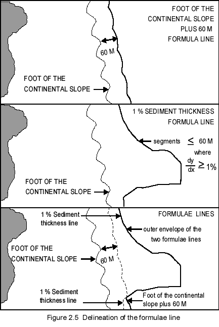
(i) The two limits computed by the application of each of
the affirmative rules are used to create their outer envelope or formulae
line (figure 2.5);
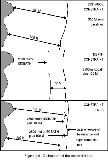
(ii) The two limits computed by the application of each
of the negative rules are used to create their outer envelope or constraint
line (figure 2.6); and
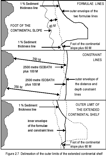
(iii) The inner envelope of the formulae and constraint
lines described above determines the outer limit of the extended continental
shelf (figure 2.7).
2.3.4. In the special case of submarine ridges, the constraint
line created in step (ii) above is formed only by the 350-nautical-miles limit.
2.3.5. Article 76, paragraph 7, describes the geometric character
of the outer limit of the continental shelf:
"The coastal State shall delineate the outer limits of its continental
shelf, where that shelf extends beyond 200 nautical miles from the baselines
from which the breadth of the territorial sea is measured, by straight lines
not exceeding 60 nautical miles in length, connecting fixed points, defined by
coordinates of latitude and longitude."
2.3.6. This provision does not specify explicitly the geometric
definition of these straight lines. Several line definitions could be
conceivably adopted. These could be, among others, loxodromes, normal
sections from either end point of a segment, or great circles. The
Commission acknowledges that this provision implements a new norm of
international law and that there is no precedent or State practice which might
suggest the existence of a uniform and extended application of a particular
geodetic methodology for this particular purpose.
2.3.7. In view of the rigorous geometric definition of a straight
line as the line of shortest distance between two points, the Commission will
employ geodesics on the surface of the official geodetic reference ellipsoid
used by a State in each submission to define the path and distances of these
specific straight lines. This decision is adopted without prejudice to,
and is independent from, the interpretation made by the Commission with respect
to straight lines as prescribed under the provisions of article 7 and as
discussed in section 3.3 of these Guidelines.
2.3.8. The length of straight lines used to connect fixed points,
which define the outer limit of the continental shelf, shall not exceed 60
nautical miles. These straight lines can connect fixed points located on
one of, or any combination formed by, the four outer limits produced by each of
the two formulae and the two constraints contained in article 76.
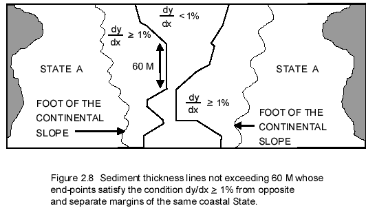
2.3.9. In the case of straight lines connecting fixed points at
each of which the thickness of sedimentary rocks is at least 1 per cent of the
shortest distance from such points to the foot of the continental slope, only
points located not more than 60 nautical miles apart along the same continental
margin will be connected. These straight lines should not be used to
connect fixed points located on opposite and separate continental margins.
This provision is implemented by the Commission with a view to ensuring that
only the portion of the seabed that meets all the provisions of article 76 is
enclosed by these straight lines. Any portion of the seabed allocated to a
continental shelf by the construction of these lines must fully meet the
requirements of the provisions of article 76. Figure 2.8
illustrates a practical example of this provision.
2.3.10. The outer limit of the continental shelf is also determined by means
of straight lines, which may connect fixed points located along arcs.
These arcs may be located at 100 nautical miles from the 2,500 metre isobath,
not more than 60 nautical miles from the foot of the slope, or 350 nautical
miles from the baselines from which the breadth of the territorial sea is
measured. In these cases, straight lines should be constructed with a view
to ensuring that only the portion of the seabed that meets all the provisions of
article 76 is enclosed.
2.3.11. The Commission acknowledges that the character of the limits
established by a coastal State based on its recommendations, according to
paragraph 8, is final and binding and that, according to paragraph 2, coastal
States shall not extend the outer limits of their continental shelf beyond these
limits:
"The continental shelf of a coastal State shall not extend beyond the
limits provided for in paragraphs 4 to 6."
The
graphic files in this document have been saved as "thumbnails" to
facilitate downloading of the document. "Click" on the small
image to expand it in a new browser window. It is suggested that you print
the figure from that new window.
3. Geodetic
methodologies and the outer limits of the continental shelf
3.1. Formulation of the problem: paragraphs 1, 4, 5
and 7
3.2. Units, geodetic reference systems and coordinate
transformations
3.3. Geodetic definition of baselines
3.4. Outer limits and their confidence zones
3.1.1. The Commission on the Limits of the Continental Shelf recognizes
that the Convention poses specific scientific requirements in the field of
geodesy. States are requested to delineate the outer limits of the
extended continental shelf based on different distance criteria. These
criteria are applied from baselines from which the breadth of the territorial
sea is measured, the foot of the continental slope and the 2,500 metre isobath.
3.1.2. Article 76, paragraph 1, establishes the right of coastal States
to determine the outer limits of the continental shelf by means of a
200-nautical-mile distance criterion from baselines:
"The continental shelf of a coastal State comprises the sea-bed and
subsoil of the submarine areas that extend beyond its territorial sea
throughout the natural prolongation of its land territory to the outer edge of
the continental margin, or to a distance of 200 nautical miles from the
baselines from which the breadth of the territorial sea is measured where the
outer edge of the continental margin does not extend up to that
distance."
3.1.3. Paragraph 4 (a) also places the same requirement as part of the
appurtenance test:
"For the purposes of this Convention, the coastal State shall
establish the outer edge of the continental margin wherever the margin extends
beyond 200 nautical miles from the baselines from which the breadth of the
territorial sea is measured, by either: ..."
3.1.4. Paragraph 4 (a) (i) establishes the need to measure the distance
between the foot of the continental slope and a point at which the sediment
thickness produces a ratio between them of 1 per cent:
"(i) a line delineated in accordance
with paragraph 7 by reference to the outermost fixed points at each of which
the thickness of sedimentary rocks is at least 1 per cent of the shortest
distance from such point to the foot of the continental slope; or"
3.1.5. Paragraph 4 (a) (ii) establishes the need to delineate a limit
up to a distance of 60 nautical miles from the foot of the continental slope:
"(ii) a line delineated in accordance with
paragraph 7 by reference to fixed points not more than 60 nautical miles from
the foot of the continental slope."
3.1.6. Paragraph 5 poses requirements to delineate limits at distances
of 350 nautical miles from baselines, and/or 100 nautical miles from the 2,500
metre isobath:
"The fixed points comprising the line of the outer limits of the
continental shelf on the sea-bed, drawn in accordance with paragraph 4 (a) (i)
and (ii), either shall not exceed 350 nautical miles from the baselines from
which the breadth of the territorial sea is measured or shall not exceed 100
nautical miles from the 2,500 metre isobath, which is a line connecting the
depth of 2,500 metres."
3.1.7. Paragraph 6 requires, in the case of submarine ridges, that the
limit should be delineated at a distance of no more than 350 nautical miles from
the baselines. Thus, implicitly, it imposes the requirement to delineate a
limit of 350 nautical miles from the baselines:
"Notwithstanding the provisions of paragraph 5, on submarine ridges,
the outer limit of the continental shelf shall not exceed 350 nautical miles
from the baselines from which the breadth of the territorial sea is measured.
This paragraph does not apply to submarine elevations that are natural
components of the continental margin, such as its plateaux, rises, caps, banks
and spurs."
3.1.8. Article 76, paragraph 7, poses a requirement to ensure that the
straight lines which form the outer limit of the continental shelf do not extend
beyond 60 nautical miles:
"The coastal State shall delineate the outer limits of its continental
shelf, where the shelf extends beyond 200 nautical miles from the baselines
from which the breadth of the territorial sea is measured, by straight lines
not exceeding 60 nautical miles in length, connecting fixed points, defined by
coordinates of latitude and longitude."
3.2. Units, geodetic reference systems
and coordinate transformations
3.2.1. The Convention makes use of two units of length: the metre
(m) and the nautical mile (M). Both units are part of the Système
International d'Unités (SI) (Bureau International des Poids et Mesures, 1991).
The current international definition of the metre was adopted by the Conference
Générale des Poids et Mesures (CGPM) in 1983. Following the proposal
adopted by the International Hydrographic Bureau (IHB) in 1929, the
international nautical mile is a unit of length defined by the identity:
1 M = 1,852 m.
3.2.2. The Commission discourages the use of any approximation to the
above exact definition. The approximation to the nautical mile based on
the length of an arc of 1 minute of latitude should be avoided in particular.
Figure 3.1 illustrates the continuous variable length of an arc of 1 minute of
latitude as a function of latitude from the equator to either of the poles on
the ellipsoid shared by the Geodetic Reference System 1980 (GRS80) and the World
Geodetic System 1984 (WGS84).
3.2.3. The Commission feels compelled to emphasize that the
abbreviation adopted by the International Hydrographic Organization (IHO) for a
nautical mile is M and that this abbreviation applies equally in all languages
(International Hydrographic Organization, 1990, p. 22).
3.2.4. The Convention does not identify explicitly the surface over
which all distances prescribed to delineate the outer limits of maritime spaces
under national jurisdiction should be measured. Several surface options
could conceivably be available to measure them. These could be mean sea
level, the geoid or the seabed, among others. Alternatively, the chord
segment joining the two end points of a line could also be proposed as an option
to measure distances. The Commission feels that the use of any of these
options might result in the uneven application of distance criteria in the
analysis of each submission.
3.2.5. The surface of a geodetic reference ellipsoid associated with
the reference system adopted by a coastal State in each submission shall be
accepted by the Commission to determine all distances in order to ensure the
application of a uniform metric at all times. This choice ensures
consistency from a geodetic perspective and appears to be also justified under
international customary law. The Commission recognizes that there is an
established uniform State practice which demonstrates the use of this surface
for the determination of the outer limits of the territorial sea, the contiguous
zone, the exclusive economic zone and, most importantly, the continental shelf
when it is defined by means of a distance criterion up to 200 M.
3.2.6. The Commission acknowledges the requirements stated in article
76, paragraphs 7 and 9, and article 84, paragraphs 1 and 2, for the
specification of the geodetic coordinates of the outer limit of the continental
shelf. Article 84, paragraph 1, highlights in particular the requirement
to specify the geodetic datum used, to which the coordinates of the outer limit
are referred.
3.2.7. The Commission is aware of the sovereign right of each State to
make submissions in fulfilment of the above requirements, selecting for this
purpose either the geodetic reference system officially used for its national
geodetic control or nautical charting activities, or any other international
reference system adopted by the State. The Commission shall use the
geodetic reference system used by each State in the preparation of its
submission as the basis for all geodetic computations, analyses and
recommendations.
3.2.8. In the interest of ensuring that the international dissemination
of all relevant geodetic information relating to the outer limit of the
continental shelf is conducted in a manner readily recognizable by third States,
the submitting State may be required by the Commission to provide:
Coordinates of the outer limit of the continental shelf in an
International Terrestrial Reference System (ITRS) adopted by the Commission;
Transformation parameters between the reference system used in the
submission and an ITRS adopted by the Commission; and
Full information relating to the scientific methodology employed to
determine these transformation parameters.
3.2.9. The Commission acknowledges the convergence of two separate
realizations of an ITRS into a single international standard. One of these
realizations is recommended by the International Union of Geodesy and Geophysics
(IUGG) and the other by the International Hydrographic Organization.
3.2.10. IUGG recommends the use of the International Terrestrial Reference
System according to Resolution No. 2 adopted at its 20th General Assembly held
at Vienna in 1991. ITRS is monitored by the International Earth Rotation
Service (IERS). Practical realizations of ITRS are produced periodically
under the name of International Terrestrial Reference Frames (ITRF) (e.g.,
Boucher et al., 1996, 1998), which are defined by means of coordinates and their
velocities for a number of IERS sites distributed worldwide (McCarthy, 1996).
3.2.11. Whenever geodetic coordinates (φ, λ, h) are computed from ITRF-yy
positions, the ellipsoid associated with GRS80 adopted by the IUGG in Resolution
No. 7 at its 17th General Assembly held at Canberra in 1979 will be used
(Moritz, 1984).
3.2.12. IHO, on the other hand, recommends the use of WGS84 as an
international hydrographic positioning standard, according to its Technical
Resolution B1.1 and Special Publications Nos. 44 and 52 (International
Hydrographic Organization, 1988, 1993). WGS84 has been preceded by three
previous reference systems: WGS60, WGS66 and WGS72.
3.2.13. The Commission notes that for all practical purposes involved in the
determination of positions relating to a submission, ITRF94, recommended by IUGG,
and WGS84 (G873), recommended by IHO, can be regarded as equivalent realizations
of an ITRS. Geodetic coordinates referred to one system will be regarded
by the Commission as equivalent in the other.
3.2.14. The Commission highlights the value of the geodetic products made
freely available to States by the International GPS Service (Neilan et al.,
1997). The availability of clock corrections and precise ephemerides is
extremely useful in producing geodetic positions in ITRF-yy free from systematic
errors induced deliberately in the GPS satellite signal through Selective
Availability (SA).
3.2.15. The Commission acknowledges that SA remains the single most important
source of error in the determination of WGS84 positions from GPS satellite
broadcast ephemerides. The use of products from the International GPS
Service is the most inexpensive, accessible and accurate avenue to determine
WGS84 (G873) point positions through ITRF94.
3.2.16. The Commission acknowledges that the transformation of coordinates
from one reference system to another can be a very complex problem (Vanícek,
1990, 1992). Sometimes the estimation of transformation parameters has
been carried out among different realizations of the same ITRS by an
international scientific organization. Transformation parameters valid at
given epochs among the various ITRF-yy, for example, are produced by IERS
(McCarthy, 1996). The Commission regards the transformation parameters
estimated by IERS and their mathematical formulation as admissible geodetic
methodologies in a submission that involves transformations between and among
all ITRF-yy realizations.
3.2.17. However, the estimation of coordinate transformation parameters
between a national reference system and a particular realization of an ITRS is a
far more complex problem. This coordinate transformation involves
deformations in addition to a seven-parameter transformation composed of three
rigid rotations, three rigid translations and a scale change. Commission X
of the International Association of Geodesy (IAG) is currently developing
transformation methodologies between different reference systems. The
Commission acknowledges the existence of several methodologies designed in the
past to address this problem (e.g., Applebaum, 1982) and that attempts have been
made to implement them in practice, for example, between WGS84 and many local
reference systems (Defense Mapping Agency, 1984). The Commission feels
that the ultimate responsibility for the preparation of all the scientific and
technical evidence, including coordinate transformations, which supports a
submission lies with the coastal State.
3.2.18. The Commission will pay special attention to the determination of
transformation parameters and their mathematical formulation when a national
reference system different from ITRF94 or WGS84 (G873) is used in a submission
made by a coastal State. The Commission's role is limited to making a
potential request for information about the geodetic position and definition of
the baselines used in a submission made by a coastal State.
3.3.1. The Commission is not entitled by the Convention to issue any
recommendations with respect to the delineation of baselines from which the
breadth of the territorial sea is measured. Its role is limited to a
potential request for information about the geodetic position and definition of
the baselines used in a submission made by a coastal State.
3.3.2. There are only two instances in which the Commission might
request geodetic information about baselines. First, it must be satisfied
that the test of appurtenance has been positively met. Secondly, if the
350 M limit is employed as a constraint in a submission, the Commission might
also find it useful to make recommendations in relation to the methodology
employed in the delineation of this limit.
3.3.3. The Commission acknowledges that it is not entitled by the
Convention to make recommendations vis-à-vis the delineation of the outer
limits of the continental shelf up to a distance of 200 M. A submitting
coastal State will not be requested to provide any information about the
baselines that generate the portion of the limits of the continental shelf
delineated at that distance.
3.3.4. Article 5 prescribes the use of the low water line as the basis
for defining normal baselines. However, the Convention does not provide
guidance in relation to the exact meaning of this term. The Commission
acknowledges that many different definitions are used in State practice and that
some define a lower tidal datum than others. Some States use
simultaneously two or more definitions of the low water line in separate
geographic regions in view of the challenges posed to navigation by specific
regional tidal regimes. Different low water lines are used routinely to
display the profile of the coastline on official nautical charts.
3.3.5. The Commission feels that there is a uniform and extended State
practice which justifies the acceptance of multiple interpretations of the low
water line. All of them are regarded as equally valid in a submission.
3.3.6. The Commission is aware that there are different chart datum transfer
techniques designed to provide the location of the low water line at sites along
the coastline other than at tide gauge sites. The Commission may require
background technical information in relation to the methodology used by coastal
States for this purpose in each submission.
3.3.7. Articles 7, 9, 10 and 47 entitle States to delineate straight, closing
and archipelagic baselines. The Convention does not specify the geodetic
definition of these baselines. In the case of straight baselines delineated in
accordance with the provisions of article 7, at least two definitions,
loxodromes and ellipsoidal geodesics, have been adopted in State practice
(United Nations, 1989).
3.3.8. In accordance with established State practice, the Commission shall
accept the definition of straight, closing and archipelagic baselines as either
geodesics or loxodromes. However, only one line definition can be consistently
selected by a submitting State for all of its baselines. In the case of
loxodromes, the Commission shall use the definition of a line of a constant
azimuth on the surface of a geodetic reference ellipsoid (Bowring, 1985). The
Commission strongly discourages the use of apparent straight lines as literally
drawn on various paper nautical charts employing a variety of map projections.
3.3.9. The Commission remains open to consider all forms and combinations of
methods used to determine the position of baselines by a State in a submission.
The Commission may request during the consideration of a submission the
following geodetic information about baselines:
Source of the data;
Positioning survey technique;
Time and date of the survey;
Corrections applied to the data;
A priori or a posteriori estimates of random and systematic errors;
Geodetic reference system; and
Geometric definition of straight, archipelagic and closing lines.
3.4.1. The delineation of the outer limits of the extended continental shelf
according to article 76 requires the determination of up to four outer limits
delineated:
By reference to the outermost fixed points at each of which the thickness
of sedimentary rocks is at least 1 per cent of the shortest distance from
such point to the foot of the continental slope;
At a distance of 60 M from the foot of the slope;
At a distance of 350 M from baselines from which the breadth of the
territorial sea is measured; and
At a distance of 100 M from the 2,500 m isobath.
3.4.2. Boggs (1930) originally defined the technique used to determine the
outer limits of the territorial sea from a selection of points along baselines
as the method of envelopes of arcs. It was first introduced as a proposal for
codification in international law by the United States delegation at the Hague
Codification Conference in 1930. This method provides an outer limit every point
of which is located at a prescribed distance from the nearest point on the
coast. Shalowitz (1962, p. 171) has advanced a more refined definition of this
method, where the outer limit:
"is the locus of the centre of a circle the circumference of which is
always in contact with the coastline, that is, with the low water line or the
seaward limits of inland waters."
3.4.3. The application of the method of envelopes of arcs is independent of
the actual breadth of the limit. Thus, although the method was originally
designed as a tool to determine the outer limit of the territorial sea, its
mathematical application remains equally valid to determine the outer limit of
other maritime spaces based on metric criteria.
3.4.4. The Commission regards the application of the method of envelopes of
arcs on the surface of the geodetic reference ellipsoid in a submission as an
admissible methodology to determine outer limits based on distances from the
nearest points located on baselines, the 2,500 m isobath and the foot of the
continental slope. The actual implementation of this method is carried out by
solving iteratively a system of linearized distance equations in a resection
mathematical model. An exhaustive combinatorial search algorithm is recommended
in order to ensure that all possible combinations of pairs of points are
analysed and that the nearest points are the ones which generate the outer
limit.
3.4.5. The distance resection model described above relies on the solution of
the direct and inverse positioning problems formulated in geodesy. A large
number of solutions to these classic problems have been developed over the last
two centuries. They can be broadly classified into three groups, based upon: the
integration of differential equations; transferring an ellipsoid polar triangle
to a concentric sphere; and using a conformal projection from the ellipsoid to
the sphere (Schnadelbach, 1974). The Commission does not have a preference for
the use of a particular solution and it is aware that the correct application of
several of them must produce identical results.
3.4.6. The Commission acknowledges the existence of the method of tracés
parallèles to determine the outer limits of maritime spaces from
straight baselines as prescribed by the International Court of Justice in the Anglo-Norwegian
Fisheries case of 1951. This method is a generalization of the method of
envelopes of arcs for the cases of continuous straight, closing and archipelagic
baselines.
3.4.7. The Commission regards the application of the method of tracés
parallèles on the surface of the geodetic reference ellipsoid used in
each submission as an admissible methodology to determine outer limits at
distances of 200 M and 350 M from the nearest points located on straight,
closing and archipelagic baselines from which the breadth of the territorial sea
is measured.
3.4.8. The mathematical model for the determination of outer limits from
straight baselines on the surface of a geodetic reference ellipsoid is
computationally more intensive than the method of envelopes of arcs. It involves
the successive application of the direct and inverse problems described above
over a large series of discrete points along straight, closing and archipelagic
baselines.
3.4.9. For the sake of simplicity, the two formulations described above have
not made any reference to the introduction of a priori statistical information
about the position of the baselines. In practice, this information must be
incorporated in order to derive the confidence region associated with the limit
(Sjoberg, 1996). It is clear, however, that the derived offshore limit will
never surpass the accuracy of the positions of the baselines themselves, and
therefore those States aiming to achieve the highest standards of accuracy in
the determination of their outer limits should focus first on the accuracy of
their baselines.
3.4.10. The Commission strongly discourages the application of the methods of
envelopes of arcs and tracés parallèles through the use of
manual graphical procedures on the surface of paper nautical charts. The
distortions produced by inherent scale factors in map projections and the
inapplicability of Euclidean geometry principles on the surface of a geodetic
ellipsoid rule out the admissibility of this manual methodology.
3.4.11. The Commission highlights three observations made by Gidel (1932, p.
510) more than half a century ago: first, that there is no parallelism between
the coast and the limit; secondly, that the outer limit is simpler than the
normal baseline; and, most importantly, that only a few points contribute to the
delineation of the outer limit. There may be no need to submit the data on the
full extent of the coastline, a full 2,500 m isobath or the continuous foot of
the slope. Only the most seaward points which effectively contribute to the
delineation of the outer limit need to be supported.
4.1. Formulation of the problem: paragraph 5
4.2. Sources of data and hydrographic measurements
4.3. Bathymetric model
4.4. Selection of points for the delineation of the 100 M limit
4.1.1. The Commission recognizes that the 2,500 m isobath is an essential
feature for the implementation of article 76. It serves as the basis for the
application of one of the constraint rules to the formulae lines in order to
produce the outer limits of the continental shelf. According to paragraph 5, it
is the reference baseline from which the 100 M line is measured:
"The fixed points comprising the line of the outer limits of the
continental shelf on the sea-bed, drawn in accordance with paragraph 4 (a) (i)
and (ii), either shall not exceed 350 nautical miles from the baselines from
which the breadth of the territorial sea is measured or shall not exceed 100
nautical miles from the 2,500 metre isobath, which is a line connecting the
depth of 2,500 metres."
4.1.2. A line determined at a distance of 100 M from the 2,500 metre isobath
may not be used in the delineation of the outer limits of the extended
continental shelf in the special case of submarine ridges. Paragraph 6 makes an
exception of submarine elevations where it is required:
"Notwithstanding the provisions of paragraph 5, on submarine ridges,
the outer limit of the continental shelf shall not exceed 350 nautical miles
from the baselines from which the breadth of the territorial sea is measured.
This paragraph does not apply to submarine elevations that are natural
components of the continental margin, such as its plateaux, rises, caps, banks
and spurs."
4.2. Sources of data and hydrographic
measurements
4.2.1. The complete bathymetric database used in the delineation of the 2,500
m isobath in a submission may only include a combination of the following data:
4.2.2. The Commission will consider single- and multi-beam echo sounding
measurements as the primary source of evidence for the delineation of the 2,500
m isobath. All other admissible evidence provided by bathymetric and
interferometric side-scan sonar measurements and seismic reflection-derived
bathymetric measurements will be regarded as complementary information in
general.
4.2.3. However, bathymetric information derived from seismic reflection and
interferometric side-scan sonar measurements may be considered as the primary
source in a submission for the purpose of delineating the 2,500 m isobath in
special cases such as in ice-covered areas. The Commission may pay particular
attention to the calibration and corrections applied to these data.
4.2.4. Bathymetric side-scan sonars are hybrid measuring systems, which
collect both estimates of sea-floor slope and bathymetry. Whereas their
sea-floor slope information might be relevant in other parts of a submission,
potentially for the delineation of the foot of the slope, only their bathymetric
component will be considered for the purpose of delineating the 2,500 m isobath.
4.2.5. The bathymetric data produced by light-detection-and-ranging (LIDAR)
airborne systems may be particularly valuable to provide bathymetric information
for the shallow regions of the seabed included in a submission. However, laser
(light amplification by stimulated emission of radiation) profiling is clearly
inapplicable to the delineation of the 2,500 m isobath, or the seabed region
associated with the base of the continental slope.
4.2.6. Other sources of evidence, such as satellite altimetry-derived
bathymetric data or imaging side-scan sonar information, will not be regarded as
admissible for the purpose of delineating the 2,500 m isobath. This information,
however, might be useful as additional qualitative information in support of
other parts of a submission but will not be considered during the determination
of this or any other isobaths. However, this data will be considered admissible
as supporting information in a submission.
4.2.7. A full technical description of the bathymetric database used in the
delineation of the 2,500 metre isobath will include the following information:
Source of the data;
Sounding survey techniques and classification;
Geodetic reference system, navigational positioning methods and their
errors;
Time and date of the survey;
Corrections applied to the data, such as ray path sound velocity,
calibration, tides and other; and
A priori
or a posteriori estimates of random and systematic
errors.
4.2.8. A priori depth error estimates, s, may be computed by means of
the following internationally accepted formulae:
s = ( a2 + ( b d )2 )1/2
where:
a
constant depth error, i.e., the sum of all constant errors
bd
depth-dependent error, i.e., the sum of all depth-dependent
errors
b
factor of depth-dependent error; and
d
depth
with a 95 per cent confidence interval (IHO, 1998).
4.2.9. A posteriori errors may be obtained from the estimated covariance
matrix of the estimated depth parameters, which results from an adjustment of an
overdetermined system of linear equations formed by cross-over analysis of
sounding lines (cf. Vanícek and Krakiwsky, 1982, p. 213).
4.2.10. Coastal States may use the a posteriori error estimation method where
there is redundant information in order to assess the quality of historical
bathymetric data whose positioning, survey technique and technical description
are not available.
4.3.1. The submission will include the necessary cartographic products
derived from the compiled bathymetric database to portray the 2,500 metre
isobath. These cartographic products may include the following analytic or
digital forms:
Two-dimensional bathymetric profiles;
Three-dimensional bathymetric models;
Nautical charts and maps with contours.
4.3.2. Each cartographic product, including nautical charts officially
recognized by the State, will be accompanied by a detailed description of the
mathematical methodology and data used to produce it. The Commission will pay
particular attention to the transit from numerical soundings to analytical
functions.
4.3.3. The coastal State will be required to document the following
information:
Interpolation or approximation method;
Density of measured bathymetric data;
Perceptual elements such as map projections, vertical and horizontal
scales, contour intervals, units, colours and symbols.
4.3.4. Wherever the bathymetric information presented to the Commission may
be a filtered or smoothed subset of the original data, a full description of the
methodology employed to produce it will be reported by the coastal State.
4.3.5. Full bathymetric models in three dimensions may be required in order
to gain a spatial understanding of natural prolongation and may be essential in
selecting the full extent of the 2,500 m isobath relevant to the determination
of the 100 M outer limit.
4.3.6. The Commission is aware that the seabed can exhibit fractal properties
in two and three dimensions (Mandlebrot, 1977). It is also aware that the
generation of an analytical model, be it that described by means of contours on
a chart or a mathematical expression, results in the generalization of line and
surface features at various scales (Fox and Hayes, 1985). The Commission may
require geostatistical, fractal, wavelet or other tests and analyses, as it
feels appropriate, in order to determine the degree of uncertainty underlying a
particular bathymetric model.
4.3.7. The Commission is aware that issues relating to scale, colour, type
and others fall within the realm of perception. These issues will be taken into
account in order to assess correctly the perception of important technical
details.
4.4. Selection of points for the delineation
of the 100 M limit
4.4.1. The line determined at a distance of 100 M from the 2,500 metre
isobath becomes effective as a constraint over the outer limits of the
continental shelf wherever this isobath is located at a distance of 250 M or
greater from the baselines from which the territorial sea is measured.
4.4.2. The selection of the most salient points along the 2,500 m isobath for
the purpose of delineating the 100 M limit may be straightforward when isobaths
are simple. However, when isobaths are complex or repeated in multiples, the
selection of points along the 2,500 m isobath becomes difficult. Such situations
arise as a result of geological and tectonic processes shaping the present
continental margins. They can create multiple repetitions of the 2,500 m
isobath, for example, by faulting, folding and thrusting along continental
margins. Unless there is evidence to the contrary, the Commission may recommend
the use of the first 2,500 m isobath from the baselines from which the breadth
of the territorial sea is measured that conforms to the general configuration of
the continental margin.
5. Foot of the continental slope determined as the
point of maximum change in the gradient at its base
5.1. Formulation of the problem: paragraph 4
5.2. Sources of data
5.3. Filtering and smoothing
5.4. Delineation of the foot of the continental slope
5.1.1. The Commission recognizes that the foot of the continental slope is an
essential feature that serves as the basis for entitlement to the extended
continental shelf and the delineation of its outer limits. According to
paragraph 4 (a) (i) and (ii), it is the reference baseline from which the
breadths of the limits specified by formulae rules are measured:
"(i) a line delineated in accordance with paragraph 7 by reference to
the outermost fixed points at each of which the thickness of sedimentary rocks
is at least 1 per cent of the shortest distance from such point to the foot of
the continental slope; or
"(ii) a line delineated in accordance with paragraph 7 by reference to
fixed points not more than 60 nautical miles from the foot of the continental
slope."
5.1.2. Paragraph 4 (b) provides a dual regime for the determination of the
foot of the continental slope:
"In the absence of evidence to the contrary, the foot of the
continental slope shall be determined as the point of maximum change in the
gradient at its base."
5.1.3. The Commission interprets the determination of the foot of the
continental slope by means of the point of maximum change in gradient at its
base, as a provision with the character of a general rule. The fundamental
requirements posed by this provision are:
The identification of the region defined as the base of the continental
slope; and
The determination of the location of the point of maximum change in the
gradient at the base of the continental slope.
5.1.4. Its implementation will be guided by bathymetric, geomorphologic,
geologic and geophysical sources of evidence.
5.2.1. Bathymetric and geological data provide the evidence to be used in the
geomorphological analysis conducted to identify the region defined as the base
of the continental slope. Only bathymetric information will be used to determine
the location of the point of maximum change in the gradient at the base of the
continental slope.
5.2.2. The bathymetric database used in the delineation of the foot of the
slope in a submission may include only one, or a combination of the following
data:
5.2.3. The Commission will require a full technical description of the
bathymetric database used in the implementation of this provision. It will also
determine the relative value from each of these sources of data in a manner that
is consistent with that applied to the determination of the 2,500 metre isobath
(refer to section 4.2).
5.2.4. The Commission will also consider as admissible evidence synthetic
bathymetric data produced in the form of grids and profiles derived from
cartographic and analog sources officially recognized by the coastal State.
These cartographic and analog sources may only be based, in turn, on a
combination of the bathymetric measurements listed above. Synthetic bathymetric
data will be accompanied by a detailed and complete technical description of the
method applied and the bathymetric measurements used to produce the cartographic
and analog sources from which it stems.
5.2.5. The coastal State will be required to document the following
information about cartographic and analog sources:
Interpolation or approximation methods;
Spatial density and position of measured bathymetric data;
Information on perceptual elements such as map projections, vertical and
horizontal scales, contour intervals, units, colours and symbols.
5.2.6. The geological and geophysical database used in the identification of
the region defined as the base of the foot of the continental slope in a
submission may include a combination of the following sources of data:
In situ
samples and measurements;
Geochemical and radiometric data;
Geophysical measurements; and
Side-scan imagery.
5.2.7. Evidence collected as in situ core samples will be accompanied
by a complete technical description and their catalogue information will also be
enclosed. In situ measurements may include any borehole or ocean-bottom
geophysical measurements and their technical description.
5.2.8. Evidence collected in the form of geochemical and radiometric data
will also be accompanied by a full technical description and their catalogue
information will be enclosed.
5.2.9. Evidence collected in the form of geophysical measurements includes
the full range of geophysical methods, including, but not limited to, seismic,
gravity, magnetic, palaeomagnetic and side-scan sonar imagery data.
5.3.1. The Commission recognizes that filtering and smoothing of bathymetric
data might be required in order to facilitate the identification of the location
of the foot of the continental slope at the point of maximum change in the
gradient at its base. This procedure might be required in some instances because
the use of second derivatives of the bathymetric surface produces an enhancement
of all features which may obscure the exact location of the foot of the slope.
5.3.2. Filtering in signal theory presupposes a clear differentiation between
signal and noise, that is, what is to be regarded as wanted and unwanted
information. In the context of the application of paragraph 4 (b), the shelf,
the slope and the rise are signal. Any other information that obstructs the
location of these features is regarded as noise.
5.3.3. The Commission is aware that the application of some filtering
procedures presupposes the use of regularly spaced data. Bathymetric data are
seldom collected in the field at equally spaced intervals. In these instances, a
coastal State might produce a regularly spaced data set from irregularly spaced
data. The Commission is aware that there are many approaches to performing this
operation. It will pay close attention to the methodology employed to produce a
regularly spaced data set, and it might request the original irregularly spaced
data, details about the mathematical technique employed and the output comprised
of regularly spaced data.
5.3.4. The Commission is aware that filter design is a wide field and that
the frequency response functions of various filters can be very different even
if they are designed to cut off information at specific thresholds. The
Commission will pay special attention to the admittance function of the filters
used in the wavelength or wave number domain which might be applied to
two-dimensional bathymetric profiles and three-dimensional bathymetric surfaces.
5.3.5. The Commission shall not accept the artificial amplification or
enhancement of any information at wavelengths at which the bathymetric
information can be decomposed. Only the removal of unwanted noise at wavelengths
shorter than those relevant to the description of the shelf, the slope and the
rise will be regarded as admissible. The Commission might request full
disclosure of the original unfiltered information, the mathematical details of
the filter and the filtered data produced when filtering is applied.
5.3.6. Smoothing is an empirical procedure which also might have an important
role to play in facilitating the identification of the main features of the
continental margin. It might have a particularly useful application when other
bathymetric features might have similar wavelengths to those which define the
location of the foot of the continental slope.
5.3.7. The Commission is aware that the full array of empirical data
smoothing techniques is vast. It remains open to considering the application of
any smoothing technique, but it will examine closely the proper application of
each one in this context. The Commission might request full disclosure of the
original data, the mathematical details of the smoothing algorithm and the
output data.
5.4.1. The methodology used to determine the foot of the continental slope by
means of the point of maximum change in gradient at its base can be regarded
also as a two- or three-dimensional problem. This mathematical methodology has
some similarities to the second derivative technique employed in the enhancement
of potential field maps produced routinely in gravity and magnetic geophysical
prospecting. The Commission recognizes the usefulness and complementarity of the
use of both two- and three-dimensional approaches.
5.4.2. The Commission is aware of the large number of techniques and methods
available for sea-floor classification and roughness analyses (e.g., Fox and
Hayes, 1985; Stewart et al. 1992; and Herzfeld, 1993). Many methods based on,
for example, fractal and geostatistical analysis have been developed.
5.4.3. The Commission will not prescribe the use of a single mathematical
methodology based on bathymetric data for the identification of the region
defined as base of the continental slope. It will make recommendations based on
the mathematical methodology applied on a case-by-case basis, and in view of all
other geological and geophysical evidence presented by the coastal State.
5.4.4. For the purpose of identifying the region defined as the base, the
Commission defines the continental slope as the outer portion of the continental
margin that extends from the shelf edge to the upper part of the rise or to the
deep ocean floor where a rise is not developed. The rise, in turn, is the
wedge-shaped sedimentary body having a smaller gradient than the continental
slope. Many continental margins, however, depart from this ideal picture (see
chap. 6, sect. 6.2, and figs. 6.1A-6.1F),
and in such cases geological and geophysical data may be used to assist in
identifying the region referred to here as the base of the continental slope.
5.4.5. The Commission defines the base of the continental slope as a region
where the lower part of the slope merges into the top of the continental rise,
or into the top of the deep ocean floor where a continental rise does not exist.
The Commission recommends that the search for the base of the continental slope
be carried out by means of a two-step approach. First, the search for its
seaward edge should start from the rise, or from the deep ocean floor where a
rise is not developed, in a direction towards the continental slope. Secondly,
the search for its landward edge should start from the lower part of the slope
in the direction of the continental rise, or the deep ocean floor where a rise
is not developed.
5.4.6. As a general rule, whenever the base of the continental slope can be
clearly determined on the basis of morphological and bathymetric evidence, the
Commission recommends the application of that evidence. Geological and
geophysical data can also be submitted by coastal States to supplement proof
that the base of the continental slope is found at that location.
5.4.7. The determination of the location of the point of maximum change in
the gradient at the base of the continental slope will be conducted by means of
the mathematical analyses of two-dimensional profiles, three-dimensional
bathymetric models and preferably both. Methods based on a purely visual
perception of bathymetric data will not be accepted by the Commission.
5.4.8. The determination of the location of the point of maximum change in
the gradient was envisaged originally by its proponent as a two-dimensional
problem based on the mathematical analyses of two-dimensional bathymetric
profiles (Hedberg, 1976). This methodology is acceptable to the Commission with
the provision that their three-dimensional location on a bathymetric map or
nautical chart is provided at all times. The Commission recommends that the
orientation of this profile be such that it runs in a perpendicular direction to
the isobaths located at the point of maximum change in the gradient at the base
of the continental slope.
5.4.9. The Commission is aware that several three-dimensional techniques have
been designed in the past to produce a continuous trace of the foot of the
continental slope. These techniques are based on the determination of the total
curvature surface (Vanícek and Ou, 1996), the second derivative surface in the
direction of the gradient (Bennet, 1996) and other second derivative-based
analyses.
5.4.10. The Commission is also aware that the application of different
two-dimensional and three-dimensional methodologies might yield different
results in a given submission using the same data set, but it is ready to
consider the application of one or several of them. In these cases, the
Commission might perform comparative analyses of the results obtained by the
application of two-dimensional methods, three-dimensional methods or both.
5.4.11. The Commission will request a complete technical description of the
original three-dimensional bathymetric model, the details of the mathematical
methodology and the output surface and the point or line defining the foot of
the continental slope.
5.4.12. Where more than a single change in the gradient is located at the
base of the continental slope, the Commission recognizes as a general rule the
selection of the point of maximum change in the gradient as the method to
identify the location of the foot of the continental slope. The selection of any
other local change in the gradient at its base, i.e., any change other than the
maximum, will be regarded by the Commission as an exception. The justification
for the application of this exception will require the presentation of evidence
to the contrary to the general rule, as described in the following chapter.
6. Foot of the continental slope determined by means
of evidence to the contrary to the general rule
6.1. Formulation of the problem: paragraph 4 (b)
6.2. Geological and geophysical evidence
6.3. Determination of the foot of the continental slope
6.4. Considerations to be given with respect to evidence to the contrary
6.1.1. The Commission recognizes that the determination of the foot of the
continental slope is achieved as a general rule by means of the point of maximum
change in the gradient at its base. However, article 76, paragraph 4 (b), also
incorporates a possible exception when evidence to the contrary of this general
rule might be submitted by a coastal State:
"In the absence of evidence to the contrary, the foot of the
continental slope shall be determined as the point of maximum change in the
gradient at its base."
6.1.2. The Commission interprets the determination of the foot of the
continental slope when evidence to the contrary to the general rule is invoked,
as a provision with the character of an exception to the rule. This provision
not only does not oppose, but in fact complements, the general rule established
by the determination of the foot of the continental slope as the point of
maximum change in the gradient at its base. Both approaches aim to find the foot
of the continental slope at its base.
6.1.3. The complementary character of this provision is emphasized by the
fact that in addition to bathymetric and geomorphological evidence, all other
necessary and sufficient geological and geophysical evidence must also be
included as part of a submission by a coastal State.
6.1.4. The Commission feels it important to outline the breadth and scope of
the necessary and sufficient evidence which will be required from States that
might deem it appropriate to invoke this provision. The clarification of
relevant scientific terms precedes the description of this evidence below.
6.1.5. The Commission acknowledges that article 76 makes use of scientific
terms in a legal context, which at times departs significantly from accepted
scientific definitions and terminology. The trend for the creation of separate
interpretations of terms can be traced back to the work carried out for the
first United Nations Conference on the Law of the Sea by the International Law
Commission (Oxman, 1969). Article 76, paragraph 1, which defines the legal
concept of the continental shelf by means of a reference to the outer edge of
the continental margin, provides a measure of the current gap between the
juridical and the scientific use of terms.
6.1.6. The definition of the continental margin in the earth sciences had a
geomorphologic inception at the time of its adoption by various scientific
organizations (Wiseman and Ovey, 1953). Current scientific knowledge about the
nature and extent of the continental margin has evolved greatly from its
original definition. It incorporates many additional geological and geophysical
concepts within the framework provided by plate tectonics (COSOD II, 1987; ODP/JOIDES,
1996).
6.1.7. Although article 76 refers to the continental shelf as a juridical
term, it defines its outer limit with a reference to the outer edge of the
continental margin with its natural components such as the shelf, the slope and
the rise as geological and geomorphological features. According to article 76,
paragraph 1:
"The continental shelf of a coastal State comprises the sea-bed and
subsoil of the submarine areas that extend beyond its territorial sea
throughout the natural prolongation of its land territory to the outer edge of
the continental margin, or to a distance of 200 nautical miles from the
baselines from which the breadth of the territorial sea is measured where the
outer edge of the continental margin does not extend up to that
distance."
6.1.8. Article 76, paragraph 3, provides further guidance to the Commission:
"The continental margin comprises the submerged prolongation of the
land mass of the coastal State, and consists of the sea-bed and subsoil of the
shelf, the slope and the rise. It does not include the deep ocean floor with
its oceanic ridges or the subsoil thereof."
6.1.9. These paragraphs are valuable to the Commission on several grounds.
They help clarify concepts such as natural prolongation of the land territory to
the outer edge of the continental margin in the geological sense of these terms,
which require the consideration of tectonics, sedimentology and other aspects of
geology. But also, they provide guidance to the Commission in interpreting the
meaning of the term "evidence to the contrary" to the general rule if
this provision, with the character of an exception, is invoked by a coastal
State in a submission to determine the foot of the continental slope.
6.1.10. The Convention does not prescribe the application of a specific
scientific methodology to define the location of the foot of the continental
slope when evidence to the contrary to the general rule is invoked. The
Commission interprets this provision as an opportunity for coastal States to use
the best geological and geophysical evidence available to them to locate the
foot of the continental slope at its base when the geomorphological evidence
given by the maximum change in the gradient as a general rule does not or can
not locate reliably the foot of the continental slope.
6.2.1. Some continental margins consist of three elements - the shelf, the
slope and the rise - whereas others show no rise. The continental slope forms a
portion of the continental margin and extends from the shelf edge to the top of
the rise, or to the top of the deep ocean floor where no rise exists. The rise
is normally a wedge-shaped sedimentary body having a smaller gradient than the
continental slope. The rise developed predominantly in a rifted margin realm
with sufficient supply of sediments from the continent after breakup and
commencement of sea-floor spreading.
6.2.2. From a geomorphological perspective, the shelf in ideal cases is the
part of the seabed adjacent to the continent, which forms a large submerged
terrace that dips gently seaward. The breadth of the shelf depends on the
geological evolution of the adjacent continent. The continental shelf extends
seaward to the continental slope, which is characterized by a marked increase in
gradient. The base of the slope is a zone where the lower part of the slope
merges into the top of the continental rise or into the top of the deep ocean
floor, in the case where no rise exists.
6.2.3. The shelf and the continental slope have characteristics typical of
continental crust, often including thick layers of sediments. The foot and the
base of the continental slope are inseparable, and commonly lie close to the
outer edge of the continent, that is, near the place where the crust changes
from continental to oceanic.
6.2.4. The Commission is aware of the difficulties arising from the
determination of the foot of the continental slope and the edge of the
continental margin from a geological perspective. Continental crust is
compositionally distinct from oceanic crust, but the boundary between these two
crustal types may not be clearly defined. Simple subdivision of margins into
shelf, slope and rise may not always exist owing to the variety of geological
and geomorphological continental margin types resulting from different tectonic
and geological settings.
6.2.5. It is difficult to generalize the geological and geomorphological
parameters that a coastal State may consider to establish the foot of the
continental slope at its base by means of evidence to the contrary to the
general rule. However, some examples and definitions are presented here based on
evidence provided by plate tectonics. The Commission is well aware that these
considerations may not exhaust all possible geological and geomorphologic types
of continental margins as examples.
Types of continental margins
6.2.6. Over the last 20 years, geoscientific studies and activities such as
the International Deep Sea Drilling Project/Ocean Drilling Programme (DSDP/ODP)
have demonstrated the presence of a variety of continental margins (e.g. COSOD
II, 1987), which can be grouped into three major categories:
(a) Convergent (active) continental margins are
formed along plate boundaries linked to active and inactive subduction zones
often, but not always, associated with a trench (e.g. ODP/JOIDES, 1996; Bally,
1988; Taylor and Natland, 1995). The convergent continental margins comprise
three different types:
(i) The accretionary convergent continental margin consists of a
wide wedge of accreted sediments which were scraped off from the downgoing
(lower) plate (fig. 6.1A);
(ii) The poor- or non-accretionary convergent continental margin
is characterized by a poorly developed accretionary wedge. Most of the
incoming sediments are underplated beneath the upper plate or are removed by
the downgoing (subducting) plate (fig. 6.1B);
(iii) The destructive convergent continental margin shows no
accretion. Material from the upper plate is eroded ("tectonic
erosion") at the foot and from the base of the upper plate by the
subducting lower plate (fig. 6.1C);
(b) Rifted (extensional, passive) continental margins
were formed along incipient plate boundaries during continental breakup and
subsequent initial production of oceanic crust by sea-floor spreading (e.g.
Bally, 1988; Edwards and Santogrossi, 1990; von Rad et al., 1982; Coffin and
Eldholm, 1991). The category of rifted continental margins can be subdivided
into two types:
(i) The wide, thin-crusted continental margin type (rifted
non-volcanic margin) with widths of several hundreds of kilometres is
characterized by a complex system of horsts and intervening grabens and
half-grabens formed during the rifting and early drifting phases, and by a
thinned continental crust (fig. 6.1D);
(ii) The narrow, thick-crusted continental margin type (rifted
volcanic margin) is characterized by a thick lower-crustal lens with seismic
velocities in the range of 7.2-7.6 km/s, and by a huge volcanic construction
in the upper crustal level displayed in seismic sections by an average 100
km wide and several thousands of metres thick wedge of seaward-dipping
reflectors (fig. 6.1E). Results of DSDP/ODP drilling have confirmed previous
interpretations (e.g. Hinz, 1981) that the wedge of seaward-dipping
reflections consists predominantly of basaltic lavas extruded in a shallow
marine or subaerial environment. This voluminous volcanic body extending
often continuously over distances of several thousands of kilometres along
rifted continental margins was formed within a relatively short episode of
transient volcanism during initial continental breakup. Recent studies have
shown that approximately 70 per cent of the rifted Atlantic continental
margins are volcanic continental margins;
(c) Sheared continental margins were created along
zones of translational continental rupturing during continental breakup and
subsequent sea-floor spreading (fig. 6.1F).
6.3.1. Evidence to the contrary to the general rule in article 76, paragraph
4 (b), is interpreted by the Commission as a provision designed to allow coastal
States to use the best geological and geophysical evidence available to them to
locate the foot of the continental slope at its base when the geomorphological
evidence given by the maximum change in the gradient does not or can not locate
reliably the foot of the continental slope.
6.3.2. The inability of the general rule to locate the foot of the slope by
means of the maximum change in the gradient at its base can be found in a number
of scenarios. One of these scenarios can be envisaged, for example, when the
curvature of the seabed along the base of the continental slope is constant. In
this case, the maximum change in the gradient encompasses not only a point, but
also a region.
6.3.3. Another scenario where the maximum change in the gradient may not
clearly render the location of the foot of the continental slope at its base was
already identified at the end of the previous chapter. In a scenario where
irregular seabed topography reveals a number of local maxima in the change of
the gradient at the base of the continental slope, it is possible that its maximum
maximorum may not be indicative of the location of its foot.
6.3.4. In these exceptional cases, geological and geophysical evidence may be
introduced as an alternative for determining the location of the foot of the
continental slope at its base.
6.3.5. Article 76, paragraph 1, defines the breadth of the continental shelf
with a reference to the edge of the geological continental margin. The
Commission finds guidance in this paragraph to determine that any point
identified on the basis of geological or geophysical evidence as the foot of the
continental slope shall be located inside the geological continental margin.
(a) Convergent (active) continental margins
6.3.6. From a geoscientific perspective, the seaward extent of convergent
continental margins is defined either by the seaward edge of the accretionary
wedge (figs. 6.1A and 6.1B), or in the case of the destructive convergent margin
type by the foot of the upper plate and by the foot of the inner trench wall,
respectively (fig. 6.1C).
6.3.7. This distinct seaward limit or plate boundary can be determined with
acceptable accuracy by modern multi-channel seismic techniques and modern
bathymetric techniques (see chap. 8).
(b) Rifted (non-volcanic) and sheared continental margins
6.3.8. From a geoscientific perspective, the seaward limit of both the rifted
non-volcanic continental margin and the sheared continental margin is defined as
the transition between continental crust and oceanic crust created by sea-floor
spreading and related volcanic/magmatic processes. Although continental crust
has a different composition from that of oceanic crust, the boundary between the
two crustal types may not be clearly defined; sometimes gradational or oceanic
crust may even intrude into extended and downthrown continental crust.
6.3.9. Modern multi-channel and deep-penetrating seismic reflection studies
and wide-angle reflection/refraction studies in parallel with magnetic and
gravity measurements (see chap. 8) are needed to determine the location of the
transitional zone of the rifted non-volcanic continental margins and of the
sheared continental margins, especially in areas where magnetic sea-floor
spreading anomalies are not well developed.
6.3.10. Apart from drilling, sampling and coring of crustal outcrops,
including seamounts in the transitional area between continental and oceanic
crust, can provide evidence of rock type or lithology and supply material for a
variety of studies, for example, radiometric age dating, palaeontological age
correlation, geochemical-isotope chemical analyses and palaeomagnetic studies.
These results can be of use in determining the ocean-continent boundary along
rifted non-volcanic and sheared continental margins. If the foot of the
continental slope is very difficult to define on the basis of bathymetric data,
the Commission might consider the continental-oceanic transitional (COT) zone
(figs. 6.1D and 6.1F) as the place to determine the outer edge of the
continental margin. Since the transitional zone can extend over several tens of
kilometres, the Commission may consider the landward limit of the transitional
zone as an equivalent of the foot of the continental slope in the context of
paragraph 4, provided that the submitted geophysical and geological data
conclusively demonstrate that the submerged land mass of the coastal State
extends to this point.
(c) Rifted volcanic continental margins
6.3.11. Rifted volcanic continental margins are characterized by a thick low-crustal
lens with high seismic velocities in the range of 7.0-7.6 km/s and a thick
sequence of seaward-dipping reflectors (SDRS) beneath the basement surface. The
SDRS merge seaward without a sharp boundary into oceanic crust created at a
pre-existing oceanic ridge. Since the feather edge of the SDRS overlies rifted
continental crust, a major part of the rifted volcanic continental margin can be
considered as "the natural prolongation of the land territory"
(article 76, paras. 1 and 3). The seaward extent of rifted volcanic continental
margins can be defined as an area in which the SDRS terminate seaward and where
the thickness of the igneous continental crust decreases to values typical of
oceanic crust, i.e. less than 15 kilometres. Wide-angle reflection/refraction
data and magnetic and multi-channel seismic reflection measurements are needed
for determining the landward limit of the transitional zone (COT in fig. 6.1E)
of the rifted volcanic continental margins, which might be considered by the
Commission as an equivalent of the foot of the continental slope in the context
of paragraph 4.
6.3.12. Although geological (plate tectonic) considerations are very
important for coastal States in the determination of the foot of the continental
slope, geomorphological aspects must also be considered. Among geological
considerations, in addition to plate tectonics, it is recommended to consider
also the sedimentary history of the margin resulting in the depositional
build-up and geomorphological shaping of the margin.
6.3.13. The Commission understands that some coastal States may have
difficulties in obtaining the necessary data to define the oceanic-continental
crust boundary, which in some cases is not clear.
6.4.1. If a State has given evidence to the contrary to the general rule
against using the foot of the continental slope (article 76 (4) (b)) in its
submission, the Commission will deal with, inter alia, the following
questions:
(i) Is that evidence acceptable to the Commission?
(ii) Does that evidence pertain to the identification of the foot of the
continental slope? Is that evidence purely bathymetric and/or morphological?
(iii) Does that evidence include subsurface information aimed at
establishing that the limit obtained by the rule of maximum change in gradient
would not, for example, equate to the limit of the geological continental
margin?
(iv) If such evidence to the contrary is presented as part of a submission,
the Commission will request that it be also accompanied by the results of
applying the rule of maximum change in gradient.
The
graphic files in this document have been saved as "thumbnails" to
facilitate downloading of the document. "Click" on the small
image to expand it in a new browser window. It is suggested that you print
the figure from that new window.
7.1.1. The Commission is aware that oceanic and submarine ridges as well as
submarine elevations are given special attention in article 76 with respect to
issues of entitlement to an extended continental shelf and the delineation of
its outer limits.
7.1.2. Article 76 mentions three types of sea floor highs:
Oceanic ridges of the deep ocean floor (para. 3);
Submarine ridges (para. 6);
Submarine elevations (para. 6).
7.1.3. None of these terms is precisely defined. It seems that the term
"ridge" is used on purpose, but the link between the "oceanic
ridges" of paragraph 3 and the "submarine ridges" of paragraph 6
is unclear. Both terms are distinct from the term "submarine
elevations" of paragraph 6.
7.1.4. Paragraph 3 establishes that the continental margin does not include
the deep ocean floor with its oceanic ridges:
"The continental margin comprises the submerged prolongation of the
land mass of the coastal State, and consists of the sea-bed and subsoil of the
shelf, the slope and the rise. It does not include the deep ocean floor with
its oceanic ridges or the subsoil thereof."
7.1.5. According to paragraph 6:
"Notwithstanding the provisions of paragraph 5, on submarine ridges,
the outer limit of the continental shelf shall not exceed 350 nautical miles
from the baselines from which the breadth of the territorial sea is measured.
This paragraph does not apply to submarine elevations that are natural
components of the continental margin, such as its plateaux, rises, caps, banks
and spurs."
7.1.6. This seems to imply that "submarine ridges" and
"submarine elevations" are also distinct legal categories, as they are
subject to separate provisions regarding the maximum outer limit.
7.1.7. The constraints contained in paragraph 6 for submarine ridges do not
apply to submarine elevations that are natural components of the continental
margin, such as "plateaux, rises, caps, banks and spurs".
7.1.8. The distinction between the "submarine elevations" and
"submarine ridges" or "oceanic ridges" shall not be based on
their geographical denominations and names used so far in the preparation of the
published maps and charts and other relevant literature. Such a distinction for
the purpose of article 76 shall be made on the basis of scientific evidence
taking into account the appropriate provisions of these Guidelines.
7.2.1. Ridges under the sea may be formed in a variety of geological
processes, including:
Ridges formed by the sea-floor spreading and associated volcanic-magmatic
processes;
Ridges formed along transform faults and created as an inherent part of
the sea-floor spreading process;
Ridges formed by later tectonic activity resulting in uplift of oceanic
crust;
Ridges formed by volcanic activity related to the movement of crust over a
hot spot. These ridges are commonly composed of coalescing volcanic features
or seamounts and generally occur on oceanic crust;
Ridges formed by interaction of oceanic crustal plates;
Ridges formed by regional excessive volcanism related to plumes of
anomalously hot mantle;
Ridges associated with active plate boundaries and the formation of island
arc systems. They could occur as active and inactive (remnant) volcanic
arcs, and forearc and back-arc ridges. Such ridges commonly reflect
different stages in the progressive development of island arc systems and
may result from variations in factors such as the rate and direction of
convergence, and from the nature of the plate being subducted;
Ridges formed by rifting (extension and thinning) of continental crust.
This process commonly forms broader features, such as marginal plateaux and
rises, but sometimes creates elongated slivers of continental crust
separated by oceanic or highly extended continental crust.
7.2.2. This categorization of ridges is not exhaustive and complete owing to
the variety of the tectonic settings of the sea floor.
7.2.3. In scientific literature the term "oceanic ridges" is not
used in an entirely strict sense. In some cases it clearly refers to oceanic
spreading ridges only, while in others it seems to apply to all ridges composed
of oceanic basaltic rocks (i.e. the first five categories in the list above).
Transform ridges, in cases where they develop through time from a continental
crustal environment into an oceanic crustal environment, may be difficult to
classify as only one or the other along their full length. The other ridge
types, except perhaps for some back-arc ridges, have no relationship to oceanic
crust.
7.2.4. Some ridges located within the continental margins have been present
since the early evolution of the margin and have influenced it since then.
Because of their presence, sediment dispersal and thickness and the morphology
of the sea floor may have acquired a unique configuration and individualization
within the regional context.
7.2.5. It should be noted that paragraph 6 makes reference to both the
category of submarine ridges, and that of submarine elevations that are natural
components of the continental margin. At the same time, the Convention
recognizes that the provision of paragraph 6 concerning the maximum limit of 350
M applies to submarine ridges.
7.2.6. The Commission feels that the provisions of paragraphs 3 and 6 may
create some difficulties in defining ridges for which the criterion of 350 M in
paragraph 6 may apply on the basis of the origin of the ridges and their
composition.
7.2.7. For example, if the oceanic ridges include the first five types of
ridges mentioned above (composed of oceanic basaltic rocks), one may find some
examples where the ridges formed along transform faults or by later tectonic
activity infringe the continental margin of continents.
7.2.8. Some ridges (including active spreading ridges) may have islands on
them. In such cases it would be difficult to consider that those parts of the
ridge belong to the deep ocean floor.
7.2.9. Article 76 makes no systematic reference to the different types of the
earth's crust. Instead it only makes reference to the two terms: "the
natural prolongation of ... land territory" and "the submerged
prolongation of the land mass" of coastal States as opposed to oceanic
ridges of the deep ocean floor. The terms "land mass" and "land
territory" are both neutral terms with regard to crustal types in the
geological sense. Therefore, the Commission feels that geological crust types
cannot be the sole qualifier in the classification of ridges and elevations of
the sea floor into the legal categories of paragraph 6 of article 76, even in
the case of island States.
7.2.10. Therefore the Commission feels that in cases of ridges its view shall
be based on such scientific and legal considerations as natural prolongation of
land territory and land mass, morphology of ridges and their relation to the
continental margin as defined in paragraph 4, and continuity of ridges.
7.2.11. As it is difficult to define the details concerning various
conditions, the Commission feels it appropriate that the issue of ridges be
examined on a case-by-case basis.
7.3.1. The term "submarine elevations" in paragraph 6 includes a
selection of highs: "such as plateaux, rises, caps, banks and spurs".
The phrase "such as" implies that the list is not complete. Common to
all of these elevations is that they are natural components of the continental
margin. This makes it relevant to consider the processes that form the
continental margins and how continents grow. The growth of the present
continents is and/or was primarily caused by geological processes along the
continental margins (e.g., Rudnick, 1995). Consequently, the Commission will
base its views on "submarine elevations" mainly on the following
considerations:
(a) In the active margins, a natural process by which a continent grows is
the accretion of sediments and crustal material of oceanic, island arc or
continental origin onto the continental margin. Therefore, any crustal
fragment or sedimentary wedge that is accreted to the continental margin
should be regarded as a natural component of that continental margin;
(b) In the passive margins, the natural process by which a continent breaks
up prior to the separation by seafloor spreading involves thinning, extension
and rifting of the continental crust and extensive intrusion of magma into and
extensive extrusion of magma through that crust. This process adds to the
growth of the continents. Therefore, seafloor highs that are formed by this
breakup process should be regarded as natural components of the continental
margin where such highs constitute an integral part of the prolongation of the
land mass.
8. Delineation of the outer limits of the
continental shelf based on sediment thickness
8.1. Formulation of the problem: paragraph
4 (a) (i) 8.2. Relevant geophysical techniques and data 8.3. Depth conversion and thickness determination 8.4. Sources and magnitudes of error 8.5. Selection of outermost fixed points of 1
per cent sediment thickness
8.1.1. The Commission recognizes that the sediment thickness rule is one of
two equally valid formulae for entitlement to the extended continental shelf and
the delineation of its outer limits subject to the constraints contained in
paragraphs 5 and 6. Paragraph 4 (a) (i) describes this formula as follows:
"(i) a line delineated in accordance with paragraph 7 by reference to
the outermost fixed points at each of which the thickness of sedimentary rocks
is at least 1 per cent of the shortest distance from such point to the foot of
the continental slope; or ..."
8.1.2. The sediment thickness formula opens an avenue for the admission of
geophysical evidence in a submission of an extended continental shelf by a
coastal State. It has the advantage of accounting for variations in continental
rises throughout the world.
8.1.3. This formula is based on a model in which the sediments of the rise
thin gradually in a seaward direction. This model links the outer limit of the
rise to the thickness of the sediments beneath it (Gardiner, 1978).
8.1.4. A coastal State that intends to apply this provision will have to
document the position of the foot of the continental slope and the thickness of
sediments in a seaward direction from it. Geoscientists have long recognized
that a series of technical issues arises during its implementation. These relate
to the identification of the sediment/basement interface, the calculation of
sediment thickness and the variability of sediment distribution.
8.1.5. In the ideal morphological model of a passive continental margin,
these sediments belong to the continental rise. The geology and morphology of
active and sheared continental margins are more complex and usually lack the
classical rise but may still comprise considerable volumes of sediments beyond
the foot of the slope (see Chapter 6).
8.1.6. The sediments of the classical rise and other sediment wedges adjacent
to the foot of the continental slope may consist of material eroded from the
adjacent continent and deposited by turbidity and contour currents. These
sediments are mixed with pelagic and hemipelagic material and/or pyroclastics,
such as ash and lava. The sedimentary facies and morphology of the slope and
rise are often severely modified by the slumping and redeposition of sediments.
8.1.7. The rise on a passive continental margin is ideally a wedge-shaped
apron formed by sediments lying on oceanic and partly continental basements. The
sediment thickness is expected to decrease gradually from the foot of the
continental slope towards the abyssal plains of the deep ocean. The basement at
the base of the sediments may have very variable dips, but in many cases has a
gentle general dip towards the continent. However, for the purpose of
implementing paragraph 4 (a) (i), the Commission understands the term
"sediment thickness" in accordance with the following definition:
8.1.8. The sediment thickness at any location on the continental margin is
the vertical distance from the sea floor to the top of the basement at the base
of the sediments, regardless of the slope of the sea floor or the slope of the
top basement surface.
8.1.9. The thickness of sediments can be determined by means of direct
sampling and indirect methods. Direct sampling is conducted by means of
drilling. This is a very costly process, particularly in deep water, and only
gives spot values. Indirect methods include acoustic and potential field
measurements. These are less expensive, more expeditious and give a better
understanding of sediment distribution. However, they require additional
information. The method of seismic profiling, for example, needs velocity
calibration.
8.1.10. Paragraph 4 (a) (i) implies the determination of the sediment
thickness by a measurement of the depth of the top of the basement from the
seabed. This determination requires the application of methods to establish the
position and shape of the seabed relative to the top of the basement. The most
relevant combined data sets for these purposes are those derived from
bathymetric and seismic reflection and refraction measurements. The calculation
of the vertical distance between the basement and seabed surfaces (i.e. the
sediment thickness) involves a conversion of the two-way travel times of the
seismic wavelet into depth in metres.
8.1.11. In some cases, especially where seismic reflection data are of poor
quality, gravimetric and magnetic data may also be relevant for mapping the top
of the basement.
8.1.12. The Commission acknowledges that, for the coastal States located in
the southern part of the Bay of Bengal, an exception to the provisions of
paragraph 4 is provided for by the Statement of Understanding in Annex II of the
Final Act of the Third United Nations Conference on the Law of the Sea. A State
that is entitled to implement this provision, and opts to do so, is expected by
the Commission to submit data at fixed points not more than 60 M apart along the
submitted boundary line of the continental shelf to document that the thickness
of sedimentary rock is not less than 1 kilometre at each of these fixed points.
8.2.1. The Commission will regard the data provided by seismic reflection and
seismic refraction surveys as the primary source of evidence for mapping and
determining the sediment thickness. Gravimetric and magnetic data may be
provided at all times as complementary sources of evidence. These complementary
forms of evidence are particularly relevant in instances where only a
non-comprehensive seismic database may be available.
Seismic reflection data
8.2.2. A typical area of continental margin will generally have four
different types of seismic reflection data derived from:
(a) Regional government/academic/industry multi-channel seismic surveys
for reconnaissance of the continental margin;
(b) Localized and detailed 2D and 3D surveys acquired predominantly on
the shelf by the hydrocarbon industry;
(c) Localized 2D multi-channel surveys acquired by research institutions
for the preparation of scientific drilling of the International Ocean
Drilling Programme (ODP) on continental margins; and
(d) Widely spaced and scattered academic/oceanographic institution
surveys, often only recorded by means of a single-channel technique.
8.2.3. Multi-channel reflection data form a much more comprehensive source of
evidence than data collected by means of single-channel techniques. The overall
greater quality and penetration of these multi-channel data offer many
advantages for the delineation of the outer edge of the continental margin.
Single-channel data are generally of poorer quality, shallower and without
velocity information. They are less valuable and often are very randomly
distributed.
8.2.4. The Commission will regard multi-channel reflection data as the most
authoritative source of evidence for the determination of sediment thickness.
Single-channel reflection data may also be provided at all times by coastal
States as a supplementary source of evidence.
8.2.5. The Commission is aware that single-channel data might be the only
source of seismic reflection data available in some submissions. In these
instances, the coastal State will be expected to have analysed all acoustic and
potential field geophysical measurements available by means of inverse theory
techniques to help render the thickness of sediments in the outer parts of the
continental margin.
Seismic refraction data
8.2.6. Seismic refraction methods, including wide-angle reflection methods,
give information on the transmission velocities and the nature of the subsurface
rock layers. The two main features of the wide-angle method are that:
(a) It employs rather low frequency sources;
(b) The seismic rays are projected obliquely through the geological
structures.
8.2.7. The low frequencies allow good penetration. The oblique angles allow
the detection and measurement of velocity gradient zones as well as the more
abrupt changes, which show up well on reflection profiles. In typical marine
wide-angle reflection surveys on continental margins, the recording stations
(ocean bottom seismographs) are placed typically 5 km to 10 km apart, providing
a corresponding moderate accuracy of the ray trace modelling solutions, velocity
and depth estimates. Full details of the source of the data and the processing
methods utilized are required in order to determine the validity of the
interpretation presented.
Gravity
8.2.8. Geodetic measurements of the Earth's gravity field may provide
evidence in support of a submission. Gravity data can be obtained from sea-floor
gravity measurements (Beyer et al., 1966; Zumberge et al., 1994), surface marine
gravity surveys (Torge, 1989) and airborne gravity surveys (LaCoste, 1967;
Valliant et al., 1985). They can also be derived on a global basis from a
combination of multi-satellite altimetry measurements and dynamic orbital
analyses (Seeber, 1993). The combination of terrestrial and extraterrestrial
gravity estimates, via inverse theory techniques, can provide important insights
into the composition and structure of the continental margin, including the
delineation of sedimentary basins, and the modelling of sediment thickness and
deep crustal structures. Free air anomalies, in particular, may be used as a
diagnosis element in order to outline the potential outer edge of the
continental margin.
Magnetics
8.2.9. Magnetic data are particularly useful for distinguishing oceanic from
continental crust since the magnetic stripes of the oceanic crust are
unmistakable. These features led to the scientific breakthrough of the sea-floor
spreading hypothesis. Similarly to satellite-derived gravity data,
satellite-derived magnetic data can only produce intermediate- to
long-wavelength anomaly maps. These satellite-derived magnetic data can be
useful in regional compilations of marine magnetic data (Arkani-Hamed et al.,
1995).
8.2.10. Again, individual marine magnetic profiles can be modelled to gain
greater insight into the nature and depth of the oceanic and continental
basements beneath the sediments.
Mapping the top of the sediments
8.2.11. Mapping the top of the sedimentary wedge of the rise is equivalent to
mapping the seabed. Modern single-beam and multi-beam swath bathymetric
technologies provide the most accurate depth measurements of the seabed (see
chap. 4). However, this information is also collected as a by-product of seismic
reflection surveys. This by-product information may be used to gain an
understanding about the bathymetry and morphology of the sea floor wherever
hydrographic measurements are not available.
8.2.12. Seismic reflection-derived bathymetric information should be
interpolated and calibrated with that provided by hydrographic surveys wherever
possible. This correction is necessary in order to remove errors that arise
owing to the lower resolution achieved as a result of the use of lower
frequencies in seismic surveys.
8.2.13. The Commission will regard the data provided by hydrographic
bathymetric surveys as the primary source of evidence for mapping the sea floor.
Bathymetric-derived information from seismic reflection surveys may be provided
at all times by coastal States as a complementary source of evidence in a
submission. This complementary evidence is particularly relevant in instances
where only a non-comprehensive bathymetric database may be available.
8.2.14. However, seismic reflection data have the advantage that the entire
sedimentary wedge, from the top to the basement, may be interpreted in the same
data set for the purpose of determining its thickness. And for this purpose the
errors inherent to seismic-derived bathymetry are not significant.
Mapping the top of the basement
8.2.15. The basement of the sediment wedge can be oceanic, continental or a
combination of both. In the simplest cases, the sediments of the rise rest on
oceanic basement all the way from the foot of the continental slope. The oceanic
basement generally forms at an oceanic spreading ridge and consists of a
peridotitic and gabbroic root complex, an intermediate zone of basaltic dyke
intrusions and a thick series of submarine basalt lavas on top. Normally, the
formation of the oceanic crust at the spreading ridge is in the range of a few
centimetres per year in an environment of moderate sediment input. This means
that it is possible to regard the top of the uppermost lava flow as the top of
the basement.
8.2.16. In more complex cases, there may be a zone of stretched and thinned
continental basement at the base of the sediments proximal to the foot of the
slope. The sediments may comprise a pre-rift and a syn-rift sequence overlaid by
a post-rift sediment wedge (fig. 8.1). If syn-rift or
pre-rift sediments are preserved below the post-rift unconformity, these may be
included in the sediment thickness estimation.
8.2.17. The top of the oceanic and continental basements represents a sharp
increase in seismic velocities and gives high acoustic impedance contrast
relative to the overlying sediments. Much of the energy will be reflected from
this surface, and the penetration of energy into the underlying basement is
significantly reduced. This results in a very low signal-to-noise ratio of the
energy reflected from within the basement, and the internal signature of the
basement will be that of random noise. Hence, on a seismic reflection profile,
the top of the basement will stand out as a prominent reflector between the
well-defined reflectors of an overlying bedded sedimentary sequence and an
underlying, high-velocity "noisy" section of the basement. In most
cases this will be true where the top of the basement is not too deeply buried
(less than ca. 5-6 km). However, in those areas where paragraph 4 (a) (i)
applies, the total sediment thickness will usually be of the order of only 1 km
to 2 km at the critical location of the outer limit line. In this way, seismic
reflection data in most cases will be the best method of identifying the top of
the basement in the most critical areas.
8.2.18. In areas of very large sediment thickness or where seismic signals
from the top of the basement are masked by interbedded lava, one may resort to
seismic refraction methods to define the depth-to-top of the true basement. The
identification of the top of the basement is then based on an interpretation of
the velocity structure of the whole crust. An estimation of the
depth-to-basement within an acceptable range of error requires a data set of
good quality and reasonable resolution as well as some degree of calibration by
reflection data and gravity modelling. Good quality seismic refraction data may
be acquired by modern ocean bottom seismograph (OBS) techniques. The 10 km
spacing generally used between the sonobuoys may, however, prove to be too large
to provide an acceptable range of error. Experiments show that a closer OBS
spacing combined with seismic reflection data improves the resolution
considerably (Mjelde et al., 1997).
8.2.19. Modelling based on a combination of gravity and magnetic data may
also give an estimated depth-to-top of the basement in areas with thick sediment
piles and no interbedded lava or intrusions. The range of error from this method
is very large relative to the seismic methods. The error in the determination of
the depth-to-top of the basement depends upon the quality of the magnetic data,
the densities and susceptibilities used in the calculations and the relative
position of the Moho. However, in areas with ice cover or very deep basements,
modelling of a combination of a heterogeneous gravity and a magnetic data set
may be a valuable supplement to a sparse seismic database used in the mapping of
the top of the basement.
Minimum data coverage
8.2.20. Article 76, paragraph 7, states that "the coastal State shall
delineate the outer limits of its continental shelf ... by straight lines not
exceeding 60 nautical miles in length, connecting fixed points ..." This
requirement must be combined with the requirement of paragraph 4 (a) (i) that
the sediment thickness at each of the fixed points shall be at least 1 per cent
of the shortest distance to the foot of the slope.
8.2.21. The above requirement means that the minimum requirement is a data
coverage that documents the required sediment thickness at fixed points at a
spacing of maximum 60 M. In principle, the survey must be designed to prove the
continuity of the sediments from each selected fixed point to the foot of the
slope (see sect. 8.5). One way to achieve the implied minimum standard is to
select a series of well documented geophysical profiles from the foot of the
slope to their intersection with the claimed delineation line at a spacing of
less than 60 M. The seismic lines therefore need to be a maximum of 60 M apart
when planning a seismic survey for the purpose of delineating the outer limit of
the continental shelf. However, this does not allow for any deviations in the
straight-line segments. Thus, a closer line spacing may be considered in order
to give more flexibility. The allowed deviation increases with a closer line
spacing according to the approximate formula:
Line spacing in nautical miles = Cosine max. angle of deviation from
orthogonal * 60 M
(see fig. 8.2).
8.2.22. The 60 M maximum spacing requirement allows coastal States to bridge
natural indentations in the sediment thickness rather than following the
sometimes meandering path of the precisely measured feature. This may also
permit a less detailed sampling over the margin, with a possible reduction of
the costs involved in the collection and interpretation of the data. However, it
is evident that such a formal minimum data coverage could miss some important
details of the morphology of the outer limit of the continental margin, and the
resulting 1 per cent line could only be a rough approximation of the true
geological limit. Coastal States that suspect that such an approximation will be
to their disadvantage will benefit from executing more comprehensive and
detailed surveys. In general, the data coverage should reflect the complexity of
the outer margin.
8.3.1. The estimation of sediment thickness requires the depth conversion of
the interpreted profiles and maps. This depth conversion of the interpreted
geophysical data should be documented by the relevant database and the
description of the method applied.
Seismic velocity
8.3.2. Determination of sediment thickness from seismic profiles requires
knowledge of the propagation velocity of the seismic signal through the
sedimentary section. This velocity can be calculated during the processing of
multi-channel seismic data, but owing to uncertainties involved in the
procedure, inaccuracies in the calculated interval velocity, and therefore
sediment thickness, could typically be 10 per cent.
8.3.3. The velocity of transmission of the acoustic wave through the
sub-seabed layers is required not only to determine their thickness, but also to
give an indication of the nature of the material. Lower velocities are generally
associated with sedimentary material, whereas higher velocities are often
associated with metamorphic, igneous or "basement" material. A
distinct change in velocities may assist in identifying the base of the
sedimentary section.
8.3.4. Velocities of the offshore sedimentary sequence can be obtained by the
following methods:
(a) In situ velocity surveys carried out in boreholes;
(b) Measurement of velocity in cores drilled in the sedimentary section;
(c) Analyses of multi-channel seismic reflection data;
(d) Seismic refraction and wide-angle reflection data analysis.
In situ and core measurements are accurate, but rare, and are only
locally significant.
8.3.5. In the case of seismic reflection data, the interval velocities are
derived from seismic stacking velocities using the Dix equation.1/
Such results are extensive but inherently somewhat inaccurate and only valid to
a depth that is related to the length of the receiver array, and are generally
more accurate at shallower depths. The accuracy is also related to the geometry
and altitude of the reflecting interfaces.
8.3.6. Analysis of seismic refraction and wide-angle reflection data can be
used to obtain the velocities of the various major layers, but the derived
velocities are averaged over the length of the refraction spread.
8.3.7. The sparsity of samples collected by the Deep Sea Drilling
Project/Ocean Drilling Programme throughout the continental margins of the world
and the lack of full seismic refraction data coverage point to the seismic
velocity data as the most relevant source of information to be collected in
order to develop velocity models in most cases.
8.3.8. The Commission regards the combined use of refraction and reflection
seismic data as the primary source of evidence to estimate propagation
velocities throughout the sedimentary wedge. Other forms of velocity estimation
may also be provided at all times by coastal States as a complementary source of
evidence.
1/ The Dix equation states that, for reflections from a sequence of flat,
parallel layers, the velocity in the nth layer Vn
(interval velocity) is given by:
Vn = [ (Wn2 * tn - Wn-12
* tn-1) / (tn - tn-1) ]½
where Wn-1 and Wn are the average velocities from the
datum to reflectors above and below the layer and tn-1 and tn
are reflection arrival times.
Depth conversion of seismic data
8.3.9. Depth conversion of seismic data requires velocity data to build a
velocity model for the sediment wedge. Such velocity models describe the
vertical and/or the lateral variation in seismic propagation velocities within
the sedimentary sequences.
8.3.10. All of the available velocity data need to be combined to generate
the most comprehensive velocity model for the sedimentary sequence on the
continental margin. This would generally be in the form of an interval velocity
map/profile or a series of interval velocity maps/profiles, together with a
listing of the seismic velocity data, including a brief description of how they
were derived, where they apply and an estimate of their accuracy. Where the
sedimentary sequence is thick and/or is well known, it may be appropriate to
build a more complex multi-layer velocity model that deals separately with
distinct sedimentary intervals.
8.3.11. The Commission recommends that the relative range of error inherent
in the velocity analysis/velocity picks be presented by coastal States in areas
where there are no borehole data for calibration of the Dix interval velocities
with respect to real propagation velocities. This may be done by presenting the
standard deviation (in Dix interval velocities) for each interval velocity
applied in the velocity model.
8.3.12. The normal approach for depth conversion would be to multiply the
previously derived time isopach map (or two-way time profile) for the total
sediment thickness from the seabed to the top of the basement with the velocity
model to arrive at the total sediment thickness. Different outputs might be
obtained in general as a result of this operation if the calculations are based
on the product of point measurements, or instead the calculations are based on
the product of the two contoured surfaces. The former method would seem
preferable to the latter.
8.3.13. At the current stage of software development, new techniques (e.g.,
iterative ray-tracing simulation, pre-stack migration processing) may be a real
alternative for some States in the depth conversion of seismic data (both
seismic reflection and seismic refraction data). The application of these
methods may have real advantages in areas with complex structures and
significant velocity anomalies. However, the Commission will consider any depth
conversion method the coastal State opts to apply to their data.
8.3.14. The Commission will have to determine the weight it gives to the
different types of evidence on a case-by-case basis. It will have to check
whether errors have occurred in calculating the sedimentary thicknesses and, if
so, whether they were attributable solely to the available velocity control or
some other source. The Commission will also have to verify whether the
sedimentary extrapolation has been applied correctly from the location of the
foot of the continental slope.
Gravity and magnetic data
8.3.15. The inversion of gravity and magnetic data is not as straightforward
as that of seismic data. The existence, uniqueness and optimization of the
solution must be analysed. The final output of this inversion is a physical
model of the sedimentary wedge that fits all the observations in an optimal way.
When the uncertainties in the resulting model are unacceptable, additional data
are incorporated in an iterative process.
8.3.16. Whereas bathymetry plays an important role in the three-dimensional
modelling of gravity data, the inversion of magnetic data into an analytical
signal is essential to define the position of the magnetic source. The final
output physical model from an inversion is often very sensitive to inaccuracies
in the measured data. The quality of the data is of prime importance in order to
ensure the reliability of depth conversion in potential field methods.
8.3.17. The depth data obtained from both gravimetric and magnetic methods
should be documented with all the modelling parameters used and a description of
the inverse methods applied as well as an assessment of the quality of the data
involved in the determinations.
8.4.1. The two most important variables in the determination of sediment
thickness are the depth estimates of the top of the basement and the velocity
model used for the depth conversion of seismic data.
Depth estimate of the top of the basement
8.4.2. In many areas the top of the oceanic or continental basement is
readily identified by a clear reflector on seismic surveys, owing to its large
impedance contrast, in areas where sediment cover is moderate (< 3-4 km). The
possibility of selecting the wrong reflector in such areas is low. Thus, the
uncertainty in the definition of the top of the basement is also low.
8.4.3. In areas of intercalated lava flows and intrusive magmatic rocks that
mask the seismic reflection from the basement surface, the definition of the top
of the basement may not be satisfactorily achieved by seismic reflection alone.
The application of additional geophysical techniques is necessary. The best
supplementary and/or alternative method is probably provided by seismic
refraction methods, and ocean bottom seismograph (OBS) methods in particular. In
addition, interpretations of the velocity structure of the subsurface based on
refraction seismic data are often constrained by gravity modelling of the
density structure. The uncertainty in the definition of the top of the basement
by refraction data is equal to the uncertainty in the depth conversion based on
those data. The range of error in depth to the basement based on a modern OBS
data set is typically of the order of 10 per cent to 20 per cent (Mjelde et al.,
1997).
Depth conversion of seismic data
8.4.4. The magnitude of errors in the converted depth of an interpreted
seismic section is directly proportional to the magnitude of errors in the
velocity model applied in the conversion. The magnitude of errors in velocity
models based on stacking velocities of seismic reflection data is typically 5
per cent to 15 per cent, depending on the depth and dip of the reflectors
interpreted, the quality of the velocity analysis and, to an extent, on the data
processing. In general, the combination of shallow depths and good quality
velocity analysis results in small errors in depth estimates.
8.4.5. In an iterative ray-tracing process, the magnitude of error in depth
estimates is a function of how close it is possible to fit the calculated to the
observed travel times.
8.4.6. The Commission will require documentation of the expected ranges of
error to be submitted by a coastal State along with a description of the
conversion methods applied.
Propagation of thickness errors to position errors
8.4.7. The expected error in the estimated thickness propagates into errors
in the position of the 1 per cent sediment line, regardless of the depth
conversion method applied.
8.4.8. The 1993 study entitled Definition of the Continental Shelf
(United Nations, 1993) briefly mentions the calculation of the magnitude of
error in horizontal distance owing to error in the calculation of sediment
thickness. The Commission proposes a more sophisticated method by applying the
following formula, which also takes into account the slope of the seabed and the
dip of the top surface of the basement:
ΔX = ΔY /(tan (b
+ θ ) + tan α)
where ΔX is the error in distance, ΔY is the error in thickness, θ is the
angle of dip of the top of the basement, α is the slope of the sea floor and b
is the angle between the top of the basement and the 1 per cent line
(i.e., the line showing the thickness increasing by 1 per cent of the distance
from the starting point). For the normal range in gradient of the rise
(between 0.07° and 1.15°
) and with a 0.2° dip of the top of the basement
towards the continent, an error of ±100 m in thickness translates to between ±7
km and ±3 km error in distance. From figure 8.3 it can be seen that the error
in distance decreases as the dip of the base of the sediments towards the foot
of the continental slope increases (θ increases). The same effects appear when
keeping the top of the basement fixed and imagining varying degrees of slopes of
the ocean floor: steepening of the ocean floor leads to smaller ranges of error
in distance (α increases).
8.5. Selection of outermost fixed points of 1
per cent sediment thickness
8.5.1. Paragraph 4 (a) (i) establishes the requirement of a line delineated
in accordance with paragraph 7 by reference to the outermost fixed points at
each of which the thickness of sedimentary rocks is at least 1 per cent of the
shortest distance from such point to the foot of the continental slope. This
implies that the sediment thickness at each fixed point must be documented by
data acquired at that location by either borehole, seismic or other geophysical
data. Locating the fixed points on the basis of an isopach map is not an
acceptable procedure to the Commission since the interpolation inherent in the
contouring introduces a new source of uncertainty and it is not strictly covered
by paragraph 4 (a) (i).
8.5.2. A jagged sea-floor and/or basement surface may cause large local
variations in sediment thickness. This is a typical feature of oceanic and
rifted continental basements. In these cases, the sediments in the area of the
outer limit of the continental margin may, over a relatively short distance,
repeatedly vary from the required thickness to less than the required thickness.
This bathymetric and geological scenario may then produce several locations
where the requirement for a 1 per cent or greater sediment thickness is
satisfied along the same profile.
8.5.3. The Commission is guided here by paragraph 4 (a) (i), which states
that the line shall be delineated by reference to "the outermost fixed
points at each of which the thickness of sedimentary rocks is at least 1 per
cent ..." The Commission invokes a principle of continuity in the
implementation of this provision to state that:
(a) To establish fixed points a coastal State may choose the outermost
location where the 1 per cent or greater sediment thickness occurs within and
below the same continuous sedimentary apron; and that
(b) For each of the fixed points chosen the Commission expects
documentation of the continuity between the sediments at those points and the
sediments at the foot of the continental slope.
8.5.4. Locating the fixed points based on a calculated distributed average
sediment thickness is not regarded as an acceptable solution to the problem of a
jagged topography.
8.5.5. Another aspect of paragraph 4 (a) (i) is the measurement of distance:
"the outermost fixed points at each of which the thickness of sedimentary
rocks is at least 1 per cent of the shortest distance from such point to the
foot of the continental slope". By "the shortest distance" the
Commission understands: the shortest distance measured along a geodesic on the
surface of the ellipsoid associated to the geodetic reference system used by the
coastal State in the submission.
The
graphic files in this document have been saved as "thumbnails" to
facilitate downloading of the document. "Click" on the small
image to expand it in a new browser window. It is suggested that you print
the figure from that new window.
9. Information on the limits of the extended
continental shelf
9.1. Formulation of the problem: paragraph 8 and Annex II
9.2. Bathymetric and geodetic data
9.3. Geophysical and geological data
9.4. Digital and non-digital data
9.5. Checklist of relevant supporting information and data
9.1.1. The Commission acknowledges that coastal States have an obligation to
submit information on the limits of the extended continental shelf for the
purpose of making recommendations. Paragraph 8 describes this obligation as
follows:
"Information on the limits of the continental shelf beyond 200
nautical miles from the baselines from which the breadth of the territorial
sea is measured shall be submitted by the coastal State to the Commission on
the Limits of the Continental Shelf set up under Annex II on the basis of
geographical representation. The Commission shall make recommendations to
coastal States on matters related to the establishment of the outer limits of
their continental shelf. The limits of the shelf established by a coastal
State on the basis of these recommendations shall be final and binding."
9.1.2. The Commission recognizes that one of its two functions prescribed in
Annex II is to consider the data and material submitted by coastal States and to
make recommendations in accordance with article 76 and the Statement of
Understanding of 1980. Annex II, article 3 (1) (a), describes this function as
follows:
"1. The functions of the Commission shall be:
(a) to consider the data and other material submitted by coastal States
concerning the outer limits of the continental shelf in areas where those
limits extend beyond 200 nautical miles, and to make recommendations in
accordance with article 76 and the Statement of Understanding adopted on 29
August 1980 by the Third United Nations Conference on the Law of the
Sea".
9.1.3. The submission will be divided in three separate parts in accordance
with the Modus Operandi of the Commission (CLCS/L.3). The requested format
contains an executive summary (22 copies), a main body (8 copies)
and all supporting scientific and technical data (2 copies).
9.1.4. The executive summary will contain the following information:
(a) Charts at an appropriate scale and coordinates indicating the outer
limits of the continental shelf and the relevant territorial sea baselines;
(b) Which provisions of article 76 are invoked to support the submission;
(c) The names of any Commission members who gave advice in the preparation
of the submission; and
(d) Any disputes as referred to in rule 44 and annex I to the Rules of
Procedure of the Commission.
9.1.5. The main body will contain a detailed description of the data set,
maps, technical procedures and scientific methodologies applied in the
implementation of article 76. References to the basic data will be documented at
each relevant step.
9.1.6. The third part will contain a copy of all data referred to in the main
body, which will be arranged in separate annexes. All data submitted by the
coastal State in support of its submission will be considered by the Commission.
9.2.1. The complete bathymetric data set used in the preparation of a
submission may include any of the following measurements, or a combination
thereof:
(f) Light detection and ranging (LIDAR) measurements.
9.2.2. This information will be included in the second and third parts of the
submission. Whereas only a part of it may be needed in the main body, the
full bathymetric database will be regarded as an essential component of the supporting
scientific and technical data.
9.2.3. The complete bathymetric data set used in the submission will be
included by the coastal State in its third part as an annex. This information
can be made available to the Commission in an analytical form as compilation
charts depicting soundings or, whenever possible, in digital form in a
Hydrographic Information System (HIS) database by means of coordinates of
latitude, longitude and depth.
9.2.4. Bathymetric data should be processed as much as possible to represent
the correct depth. Spurious depth measurements should have been edited out.
9.2.5. A full technical description of the bathymetric database will include
the following information:
Source of the data;
Sounding survey techniques and their technical specifications;
Geodetic positioning methods and reference system;
Time and date of the survey;
Corrections applied to the data for speed of sound in water, calibration
and other;
A priori or a posteriori estimates of random and systematic errors;
Geodetic reference system;
Geometric definition of straight, archipelagic and closing baselines.
9.2.6. The main body of the submission will include all the necessary
cartographic products derived from the compiled bathymetric database. These
cartographic products may include the following analytic or digital forms:
Two-dimensional depth profiles;
Three-dimensional bathymetric models;
Charts and maps with contours.
9.2.7. Each cartographic product will be accompanied by a detailed
description of the mathematical methodology and bathymetric data used to produce
it. The Commission will pay particular attention to the transit from numeric
soundings to analytic functions. The coastal State may be requested by the
Commission to document the following information:
Interpolation or approximation method;
Density of measured bathymetric data;
Perceptual elements such as map projections, vertical and horizontal
scales, contour intervals, units, colours and symbols.
9.2.8. Wherever the bathymetric information presented to the Commission may
be a filtered or smoothed subset of the original data, a full description of the
methodology employed to produce it will be reported by the coastal State.
Geodetic data
9.2.9. Coastal States will be requested to provide information about the
geodetic reference system used in the submission. Coordinate transformation
parameters from this system to ITRF94 or WGS84 (G873) will be requested whenever
one of these systems is not used in a submission.
9.2.10. Geodetic information may need to be included about some baselines
from which the breadth of the territorial sea is measured. This will be the case
only for those baselines which define a line at a distance of 350 M, if this
constraint is applied at all to define the outer limits of the continental
shelf. The following information may be requested by the Commission:
Source of the data;
Geodetic positioning technique and reference system;
Corrections applied to the data;
Geodetic definition in the case of straight or archipelagic baselines;
A priori or a posteriori estimates of random and systematic errors;
Geodetic reference system;
Geometric definition of straight, archipelagic and closing baselines.
9.3.1. Seismic data may include both seismic reflection and seismic
wide-angle reflection/refraction data.
9.3.2. The submission ought to include a list of all seismic surveys used in
relation to the submission. This should be supplemented with one or several maps
showing the line coverage of each survey. Several surveys may be combined in one
map provided that the distinction between them is indicated.
9.3.3. Navigation and data records should be annotated in the same units.
Multi-channel seismic reflection lines are usually annotated in shot points,
common depth points (CDPs) or both. These are not interchangeable, and should
accordingly be labelled clearly.
9.3.4. Seismic lines must be tied to a navigation plot and annotated in the
same units as the seismic line (shot points, CDPs).
9.3.5. Multi-channel seismic data should be processed to at least the
necessary level of quality to justify the particular approach used. A
description of the acquisition parameters and the processing sequence should
either appear on the individual seismic line or be included separately for each
survey in the submission. This should also include information on the cruise or
ship on which the data were collected and the dates of collection and of
processing of the data. In addition, seismic lines should have a vertical scale
in seconds, an indication of direction and an indication of horizontal scale.
9.3.6. Unmarked copies of the seismic lines are needed, together with the
interpretation of the same lines, in order for the Commission to observe the
details of the interpretation.
9.3.7. The format of analogue records is essentially the same as for digital
seismic records. The records are often annotated with time-of-day, and
navigation data with this annotation need to be provided. Vertical and
horizontal scales should be noted, as well as an indication of the direction of
the profile.
9.3.8. Seismic velocity data used for depth conversion should be submitted
together with a description of how they were derived, where they apply and an
estimate of their accuracy. This applies to both stacking velocities from
multi-channel reflection seismic and interval velocities derived from wide-angle
reflection/refraction seismic data. For the specific seismic lines that document
the sediment thickness at the outermost fixed points of the outer limit line,
the actual velocity analysis from the processing job should be submitted at
least for a part of the line where it crosses the fixed points.
Gravity data
9.3.9. The complete gravity database used in the preparation of a submission
may include a combination of:
Marine, aerial and sea-bottom gravimeter measurements; and
Gravity values derived from satellite altimetry and orbital analyses.
9.3.10. This information will be included in the second and third parts of
the submission. Whereas only a part of it may be needed in the main body,
the full gravity database will be regarded as an essential component of the supporting
scientific and technical data.
9.3.11. The complete gravity database used in the submission will be included
by the coastal State in its third part as an annex. This information can be made
available to the Commission in an analytical form as compilation maps depicting
observed values or, whenever possible, in digital form in a Geographic
Information System (GIS) database by means of coordinates of latitude, longitude
and gravity or gravity anomaly. The coastal State will be required to document
the following information:
Source of the data;
Gravity meters and their technical specifications;
Geodetic positioning methods;
Time and date of the survey;
Corrections applied to the data: tides, Eötvös and other;
A priori or a posteriori estimates of random and systematic errors;
Geodetic reference system; and
Geometric definition of straight, archipelagic and closing baselines.
9.3.12. The data should be accompanied by a description of the acquisition
parameters (including track direction, elevation and position control),
correction procedures and a contoured anomaly map which also displays the actual
data coverage.
9.3.13. Maps and profiles should be clearly marked with geodetic coordinates
and a reference to original data on which they are based (survey names).
Magnetic data
9.3.14. The complete magnetic database used in the preparation of a
submission may include a combination of:
Marine and aerial fluxgate and proton-precession magnetometer
measurements; and
Magnetic values derived from satellite observation campaigns.
9.3.15. Magnetic data may include data of varying vintages and acquisition
methods (ship or airborne). A list of all magnetic surveys and their year of
acquisition should be provided together with a map showing the outline of each
separate survey.
9.3.16. The data should be accompanied by a description of the acquisition
parameters (including track direction, elevation and position control),
correction procedures and a contoured anomaly map which also displays the actual
data coverage.
Geological data
9.3.17. In the case of evidence to the contrary, it is recommended, in
addition to the information described in the checklist in section 9.5, to
include the following data obtained from sampling and coring of crustal subcrops
at the continental margin with information about the source of the data:
Lithology;
Radiometric/palaeontological/palaeomagnetic age dating;
9.4.1. All the previous types of data may be presented as geological/
geomorphologic profiles and cross-sections. Such profiles and cross-sections
should be clearly marked with references to the specific data (seismic, gravity,
magnetic or bathymetry) on which they are based (e.g., on a geological
cross-section based on a seismic interpretation, the shot-point positions and
the identification of the seismic line may be included along the base of the
cross-section; if a cross-section consists of a combination of several segments
of different seismic lines, each of the original segments should be labelled and
the tie points between them indicated).
9.4.2. The geodetic positions of all profiles must be given, preferably on
maps. Geological/geomorphologic features shall be shown on those maps. Vertical
and horizontal scales should be noted, as well as an indication of the direction
of the profile or cross-section. Vertical axis may be in time (milliseconds) or
depth (metres).
9.4.3. In the case of depth sections based on seismic data, a description of
the velocity data and the conversion method is requested.
9.4.4. In the case of crustal structure cross-sections based on gravity data,
information on the densities and the calculation methods and software applied
must be included.
Maps and charts
9.4.5. It is recommended that the geophysical and bathymetric data and their
interpretation documenting the sediment thickness and the foot of the
continental slope be presented as a series of charts, maps, profiles and other
graphics.
9.4.6. The final graphics may vary greatly depending on the chosen vertical
and horizontal scales, and the methods of interpolation, extrapolation,
contouring and various types of digital processing. The Commission therefore
requires due references to the original data and a description of the methods
involved in order to verify the quality and reliability of a graphic
presentation.
9.4.7. An important part of any submission should be a series of maps which
ties all the data submitted into a common geodetic frame of reference. It is
reasonable to suggest that the scale and projection for all submitted maps or
groups of maps (ships' tracks, bathymetry, sediment isopach maps, depth of
basement, as well as other possible maps, such as magnetic anomaly maps, gravity
maps or wide-angle reflection/refraction lines) should be the same. Every map
should be supported by the database, preferably in digital form, from which it
was derived.
9.4.8. Latitude and longitude should be clearly marked on maps. It should be
clear whether the units are degrees/minutes or decimal degrees. Maps should be
large enough so that details of the cruise tracks are visible and track
annotations are legible.
9.4.9. In support of the executive summary to be submitted, it will be
necessary to prepare a map of the outer limits of the continental shelf,
indicating the criteria on which the submission is based. Such a map should be
on a scale suitable to fit A4 size paper and should cover the full extent of the
continental shelf, up to its outer limit.
9.4.10. The coastal State can use the colour schemes, symbology and type of
projection deemed adequate to the cartographic representation.
9.4.11. Maps, charts and databases submitted to the Commission must bear the
authentication from the national agency of the respective coastal State which is
legally authorized to certify its quality and reliability.
Digital data
9.4.12. The coastal State may use data collected with a range of techniques
from a wide variety of sources in establishing the outer limits of the
continental shelf. In recent years, however, most bathymetric and geophysical
data have been captured, processed and stored in digital form. Therefore, the
coastal State may find it convenient to submit much of its material in digital
form.
9.4.13. The coastal State can submit digital data in any internationally
recognized format.
9.5 Checklist of relevant supporting
information and data
9.5.1. The submission in support of the outer limit of the continental shelf
of a coastal State may include one of five possible cases at any point along the
limiting line:
1: A line delineated at a distance of 60 M seaward from
the foot of the continental slope (in accordance with article 76 (4) (a)
(ii)); or
2: A line along which the sediment thickness is 1 per
cent of the shortest distance from the foot of the slope (in accordance with
article 76 (4) (a) (i));
and not further than
3: A line delineated at a distance of 350 M from the
baselines; or
4: A line delineated at a distance of 100 M from the
2,500-metre isobath; or
5: A limit agreed to by States with opposite or adjacent
coasts (in accordance with article 83).
9.5.2. For each of these cases, the Commission may request that it be
provided with the information indicated under the corresponding case code in the
table below:
"Y" indicates that provision of this information is necessary for
the Commission and the subcommission to discharge their responsibilities;
"R" indicates that provision of this information is recommended
to assist the Commission and the subcommission in discharging their
responsibilities.
Cases for which this information is to be submitted
Type of information to be
submitted
1
2
3
4
5
Limit of overall continental
shelf for coastal State (map)
Y
Y
Y
Y
Y
Limit of continental shelf for
different parts of the margin (larger-scale maps)
Y
Y
Y
Y
Y
Criteria by which the limit is
defined, each of the five criteria being indicated by a coded line (map)
Y
Y
Y
Y
Y
Baselines used in defining the
limit if not shown on the limit maps (map)
-
-
Y
-
R
Baselines used for different
parts of the margin (large-scale maps)
-
-
Y
-
R
200 M limit (map)
Y
Y
Y
Y
Y
350 M limit (map)
Y
Y
Y
Y
Y
Location of the foot of the
continental slope (FOS), specifying how it was determined (map)
Y
Y
Y
Y
Y
Lines used to determine FOS
(map), showing line identifier, navigation, shot points, etc., including
the 60 M extension line
Y
Y
Y
Y
-
Lines used to define the
2,500-metre isobath (map), showing line identifier, navigation, shot
points, etc., including the 100 M extension line
Y
Y
Y
Y
R
Bathymetric contour (map):
- Where it identifies the
2,500-metre isobath
Y
Y
Y
Y
-
- Where not used as the basis
for FOS
R
R
R
R
-
- Where used as the basis for
FOS
Y
Y
Y
Y
-
- FOS base points used for 60 M
extrapolation (map)
Y
-
Y
Y
-
All bathymetric profiles
(sections) annotated with locations of the determined FOS:
- Where used as the basis for
FOS
Y
Y
Y
Y
-
- Where not used
R
R
R
R
-
Bathymetric profiles annotated
with the location of the determined FOS to indicate the character of the
margin
R
R
R
R
-
Bathymetric survey parameters
(table) keyed by cruise or line identifier showing reliability of FOS
and 2,500-metre isobath, including sound velocity used and accuracy of
location and velocity/depth profiles
Y
Y
Y
Y
-
Digital multi-channel seismic
tracks (map) used in the determination of sediment thickness, including
shot-point numbers and navigation
-
Y
-
-
-
Analog single-channel seismic
tracks (map) used in determination of sediment thickness, including shot
points and navigation
-
Y
-
-
-
FOS points used to derive the 1
per cent sediment thickness line (map)
-
Y
-
-
-
Seismic profiles (travel-time
sections) used to determine sediment thickness (two copies: one
original, one interpreted)
-
Y
-
-
-
Representative seismic profiles
(travel-time sections) used to determine sediment thickness (two copies:
one original, one interpreted) to indicate character of the margin
-
R
-
-
-
Travel-time difference between
sea floor and the basement (map)
- If 1 per cent points based on
profiles
-
R
-
-
-
Sediment thickness (map) showing
depth-converted versions of travel time difference maps
- If 1 per cent points based on
profiles
-
R
-
-
-
Survey parameters keyed to
seismic profiles (table), including the acquisition method, time/depth
conversion table/plot and accuracy indicators for location and velocity
-
Y
-
-
-
Velocity analysis (table) on
which time/depth conversion was based
-
Y
-
-
-
Location of all data used as
basis for velocity analysis (map), indicating whether refraction, ocean
bottom seismometer, sonobuoy, borehole, wide-angle reflection or other
method was used
-
Y
-
-
-
All depth-converted profiles
(sections or horizontal plots) annotated to show sea floor, basement
surface, FOS and 1 per cent points:
- If 1 per cent points based on
profiles
-
Y
-
-
-
Representative depth-converted
profiles (sections or horizon plots) annotated to show sea floor,
basement surface, FOS and 1 per cent points to indicate the character of
the margin
Alexander, L. M. (1990). Alternative Interpretations of Geographic
Articles in the 1982 LOS Convention. Center for Ocean Management Studies,
Kingston, University of Rhode Island.
Allaby, A. and M. Allaby (1991), The Concise Oxford Dictionary of Earth
Sciences, Oxford, Oxford University Press.
American Geological Institute (1976), Dictionary of Geological Terms.
Garden City, New York, Anchor Press/Doubleday.
Appelbaum, L. T. (1982). Geodetic Datum Transformation by Multiple Regression
Equations. Proceedings of the Third International Geodetic Symposium on
Satellite Doppler Positioning, New Mexico State University, Las Cruces, New
Mexico, 8-12 February, p. 207-223.
Arkani-Hamed, J.; J. Verhoef; W. Roest; R. Macnab (1995). The
intermediate-wavelength magnetic anomaly maps of the North Atlantic Ocean
derived from satellite and shipborne data. Geophysical Journal International
123, 727-743.
Bally, A. W. (ed.) (1988) Atlas of Seismic Stratigraphy. AAPG Studies in
Geology No. 27, vol. 1-3, American Association of Petroleum Geologists.
Bell, T. H. (1979). Mesoscale sea floor roughness. Deep-Sea Research
26 (1A): 65-76.
Bennet, J. O. (1996). Mapping the Foot of the Continental Slope with Spline
Smoothed Data using the Second Derivative in the Gradient Direction. Proceedings
of the Second International Conference on Geodetic Aspects of the Law of the Sea,
Bali, Indonesia, 1-4 July, p. 303-335.
Beyer, L. A., R. E. von Huene, T. H. McCullogh and J. R. Lovett (1966).
Measuring gravity on the sea floor in deep water. Journal of Geophysical
Research 71: 2091-2100.
Boggs, S. W. (1930). Delimitation of the Territorial Sea: the Method of
Delimitation Proposed by the Delegation of the United States at the Hague
Conference for the Codification of International Law. American Journal of
International Law 24 (3): 541-555.
Boucher, C., Z. Altamimi, M. Feissel and P. Sillard (1996). Results and
Analysis of the ITRF94. International Earth Rotation Service. IERS Technical
Note 20, Paris, Observatoire de Paris.
Boucher, C., Z. Altamimi and P. Sillard (1998). Results and Analysis of the
ITRF94. International Earth Rotation Service. IERS Technical Note 24,
Paris, Observatoire de Paris.
Bowring, B. R. (1985). The Geometry of the Loxodrome. Canadian Surveyor 39
(3): 223-230.
Bureau international des poids et mesures (1991). Le Système international
d'unités. Sèvres.
Carrera, G. (1992). An Iterative Method for the Investigation of Archipelagic
Status. Proceedings of the First International Conference on Geodetic Aspects
of the Law of the Sea, Bali, Indonesia, 8-11 June, p. 80-84.
Carrera, G. (1992). The Electronic Chart Display and Information System (ECDIS)
and International Maritime Boundaries. Proceedings of the First International
Conference on Geodetic Aspects of the Law of the Sea, Bali, Indonesia, 8-11
June.
Carrera, G. and R. Macnab (1996). Maritime Spaces in the Arctic Ocean: some
hypothetical and not-so-hypothetical scenarios. Presentation at the Boundaries
and Energy: Problems and Prospects Conference. International Boundaries Research
Unit, Durham, United Kingdom, 18 July 1996. Also in the Proceedings of the
Second International Conference on Geodetic Aspects of the Law of the Sea,
Bali, Indonesia, 1-4 July 1996, p. 169-182.
Coffin, M. F. and O. Eldholm (eds.) (1991). Large Igneous Provinces: JOI/USSAC
Workshop Report. University of Texas at Austin for Geophysics, Technical Report
No. 4.
COSOD II (1987): Report of Second Conference of Scientific Ocean Drilling
<COSOD II>. France, European Science Foundation (ESF).
Couper, A. D. (1989). The Times Atlas and Encyclopaedia of the Sea.
London, Times Books Limited.
Cunningham, J. and V. L. Curtis (1996). WGS84 Coordinate Validation and
Improvement for the NIMA and Air Force GPS Tracking Stations. Dahlgren
Division, Naval Surface Warfare Center, NSWCDD/TR-96/201, November 1996.
Defense Mapping Agency (1984). Department of Defense World Geodetic System
1984: Its Definition and relationships with Local Geodetic Systems. DMA
Technical Report TR 8350.2, 2nd ed. (1991).
Edwards, J. D. and P. A. Sangrossi (eds.) (1990). Divergent/Passive Margin
Basins. AAPG Memoir 48, American Association of Petroleum Geologists.
Fox, C. G. and D. E. Hayes (1985). Quantitative methods for analyzing the
roughness of the seafloor. Reviews of Geophysics 23 (1): 1-48.
Gardiner, P. R. (1978). Reasons and methods for fixing the outer limit of the
legal continental shelf beyond 200 nautical miles. Revue iranienne des
relations internationales (Tehran), Nos. 11-12, 145-170.
Gidel, G. C. (1932). Le droit international de la mer, vol. 3, p. 510.
Harsson, B. G. (1992). Baseline determination: Experiences in Norway. Proceedings
of the First International Conference on Geodetic Aspects of the Law of the Sea,
Bali, Indonesia, 8-11 June 1992, p. 31-33.
Hedberg, H. D. (1976). Relation of Political Boundaries on the Ocean Floor to
the Continental Margin. Virginia Journal of International Law 17 (1):
57-75.
Herzfeld, U. C. (1993). A Method for Seafloor Classification Using
Directional Variograms, Demonstrated for Data from the Western Flank of the
Mid-Atlantic Ridge. Mathematical Geology 25 (7): 901-924.
Hinz, K. (1981). An Hypothesis on Terrestrial Catastrophes: Wedges of very
thick oceanward dipping layers beneath passive continental margins. Geol.
Jahrbuch, Reihe E, H.22: 3-23.
International Hydrographic Organization (1993). Specifications for Chart
content and display aspects of ECDIS, 3rd ed. International Hydrographic Bureau,
Special Publication No. 52, Monaco.
International Hydrographic Organization (1998). IHO Standards for
Hydrographic Surveys, 4th ed. Special Publication No. 44, Monaco.
Kumar, M. (1992). Use of World Geodetic System 1984 as a Global Reference. Proceedings
of the First International Conference on Geodetic Aspects of the Law of the Sea,
Bali, Indonesia, 8-11 June 1992, p. 106-115.
LaCoste, L. J. B. (1967). Measurement of gravity at sea and in the air. Reviews
of Geophysics 5, 477-526.
Lapidus, D. F. (1990). Collins Dictionary of Geology. London, Harper
Collins.
Malys, S. and J. A. Slater (1994). Maintenance and Enhancement of the World
Geodetic System 1980. Proceedings of ION GPS-94, 7th International
Technical Meeting of the Satellite Division of the Institute of Navigation, Salt
Lake City, Utah, p. 17-24.
Malys, S., J. A. Slater, R. W. Smith, L. E. Kunz and S. C. Kenyon (1997).
Refinements to the World Geodetic System 1984. Proceedings of ION GPS-97,
10th International Technical Meeting of the Satellite Division of the Institute
of Navigation, Kansas City, Missouri, p. 841-850.
Mandelbrot, B. (1977). Fractals: Form, Chance and Dimension. San
Francisco, W. H. Freeman.
McCarthy, D. D. (ed.) (1996). IERS Conventions (1996). International Earth
Rotation Service. IERS Technical Note 21, Paris, Observatoire de Paris.
Macnab, R., M. Sorokin, R. Jackson and Y. Kazmin (1996). Submerged
Prolongations of the Continental Margin beyond 200 Nautical Miles in the Arctic
Ocean: Implications for Article 76 Implementations. Proceedings of the Second
International Conference on Geodetic Aspects of the Law of the Sea, Bali,
Indonesia, 1-4 July 1996, p. 365-376.
Mjelde, R., S. Kodaira, P. Digranes, H. Shimamura, T. Kanazawa, H. Shiobara,
E. W. Berg and O. Riise (1997). Comparison between a Regional and Semi-regional
Crustal OBS Model in the Vøring Basin, Mid-Norway Margin. Pure and Applied
Geophysics 149: 641-665.
Monahan, D.and M. J. Casey (1985). Contours and contouring in hydrography.
Part I - The Fundamental Issues. The International Hydrographic Review,
July, vol. LXII, No. 2, pp. 105-120.
Moritz, H. (1984). Geodetic Reference System 1980. Bulletin géodésique,
vol. 58, No. 3: 388-398.
Neilan, R. E., J. F. Zumberge, G. Beutler, and J. Kouba (1997). The
International GPS Service: A Global Resource for GPS Applications and Research. Proceedings
of ION GPS-97, 10th International Technical Meeting of the Satellite
Division of the Institute of Navigation, Kansas City, Missouri, p. 883-889.
Nordquist, M. H. (Editor-in-Chief) (1985-1993). United Nations Convention on
the Law of the Sea 1982: A Commentary. Volume I: Text of Convention and
Introductory Material. Nordquist, M. H. (ed.); Volume II: Second Committee:
Articles 1 to 85. Annexes I and II, and Final Act, Annex II. Nandan, S. N., S.
Rosenne and N. R. Grandy (eds.); Volume III: Second Committee: Articles 86 to
132, and supplementary documents. Nandan, S. N., S. Rosenne and N. R. Grandy
(eds.); Volume IV: Third Committee: Articles 192 to 278, and Final Act, Annex
VI. Rosenne, S. and A. Yankov (eds.); Volume V: Settlement of Disputes, General
and Final Provisions: Articles 279 to 320, Annexes V, VI, VII, VIII and IX, and
Final Act, Annex I, Resolutions I, III and IV. Rosenne, S. and L. B. Sohn
(eds.). Dordrecht, Martinus Nijhoff.
Ocean Drilling Program (ODP)/JOIDES (1996). Understanding our dynamic earth
through ocean drilling. Ocean Drilling Program Long Range Plan. Washington,
D.C., Joint Oceanographic Institutions, Inc.
Ou, Z. and P. Vanícek (1996). Automatic Tracing of the Foot of the
Continental Slope. Marine Geodesy 19 (2): 181-195.
Ou, Z. and P. Vanícek (1996). The Effect of Data Density on the Accuracy of
Foot-line Determination through Maximum Curvature Surface by Automatic
Ridge-tracing Algorithm. International Hydrographic Review LXXIII (2):
27-38.
Oxman, B. H. (1969). The preparation of article 1 of the Convention on the
Continental Shelf. Prepared for Commission on Marine Science, Engineering and
Resources. Springfield, Virginia, National Technical Information Service.
Price, W. F. (1986). The New Definition of the Metre. Survey Review 28
(219): 276-279.
Quine, W. V. (1966). Methods of Logic., rev. ed. New York: Holt, Rinehart and
Winston.
Rudnick, R. F. (1995). Making continental crust. Nature, vol. 378:
571-578.
Schnadelbach, K. (1974). Entwicklungstendenzen in Rechenverfahren der
mathematischen Geodäsie. Zeitschrift für Vermessungswesen 99: 421-430.
Seeber, G. (1993). Satellite Geodesy. New York, Walter de Gruyter.
Shalowitz, A. L. (1962). Shore and Sea Boundaries: with Special Reference to
the Interpretation and Use of Coast and Geodetic Survey Data. Volume 1, Boundary
Problems Associated with the Submerged Lands Cases and the Submerged Lands Acts.
Washington, D.C., U.S. Department of Commerce, Coast and Geodetic Survey.
Sjoberg, L. (1996). Error propagation in maritime delimitation. Proceedings
of the Second International Conference on Geodetic Aspects of the Law of the Sea,
Bali, Indonesia, 1-4 July 1996, p. 153-168.
Stewart, W. K., Marra, M. and M. Jiang (1992). A Hierarchical Approach to
Seafloor Classification Using Neural Networks. Proceedings of the IEEE Oceans
92 Conference, Honolulu, Hawaii, p. 109-113.
Swift, E. R. (1994). Improved WGS84 Coordinates for the DMA and Air Force GPS
Tracking Sites. Proceedings of ION GPS-94, 7th International Technical
Meeting of the Satellite Division of the Institute of Navigation, Salt Lake
City, Utah, p. 285-292.
Taylor, B. and Natland, J. H. (eds.) (1995). Active Margins and Marginal
Basins of the Western Pacific. Geophys. Monograph, vol. 88.
Torge, W. (1989). Gravimetry. New York, Walter de Gruyter.
United Nations (1983). Office for Ocean Affairs and the Law of the Sea. The
Law of the Sea. United Nations Convention on the Law of the Sea with Index and
Final Act of the Third United Nations Conference on the Law of the Sea.
(A/CONF.62/122). Sales No. E.83.V5.
United Nations (1989). Office for Ocean Affairs and the Law of the Sea. The
Law of the Sea. Baselines: National Legislation with Illustrative Maps. Sales
No. E.89.V.10.
United Nations (1993). Office of Legal Affairs: Division for Ocean Affairs
and the Law of the Sea. The Law of the Sea. Definition of the Continental Shelf.
Sales No. E.93.V.16.
United Nations (1997). Office of Legal Affairs: Division for Ocean Affairs
and the Law of the Sea. Commission on the Limits of the Continental Shelf: its
functions and scientific and technical needs in assessing the submission of a
coastal State. 10 June 1996 (SPLOS/CLCS/INF/1).
United Nations (1997). Office of Legal Affairs: Division for Ocean Affairs
and the Law of the Sea. The Law of the Sea. Official Texts of the United Nations
Convention on the Law of the Sea of 10 December 1982 and of the Agreement
relating to the Implementation of Part XI of the United Nations Convention on
the Law of the Sea of 10 December 1982 with Index and excerpts from the Final
Act of the Third United Nations Conference on the Law of the Sea. Sales No.
E.97.V.10.
United Nations (1998). Commission on the Limits of the Continental Shelf.
Rules of Procedure of the Commission on the Limits of the Continental Shelf. 4
September 1998 (CLCS/3/Rev.2).
Valliant, H. D., Halpenny, J., and Coopper, R. V. (1985). A microprocessor-
based controller and data acquisition system for LaCoste and Romberg air-sea
meters. Geophysics 50: 840-845.
Vanícek, P. (ed.) (1990). Geodetic Commentary to TALOS Manual. Appendix to
Special Publication No. 51. Monaco, International Hydrographic Bureau.
Vanícek, P. (1992). The problem of a maritime boundary involving two
horizontal geodetic datums. Proceedings of the First International Conference
on Geodetic Aspects of the Law of the Sea, Bali, Indonesia, 8-11 June 1992,
p. 97-105.
Vanícek, P. and E. Krakiwsky (1982). Geodesy: The Concepts, 2nd ed.,
Amsterdam, Elsevier, 1992.
Vanícek, P. and Z. Ou (1996). Automatic tracing of continental slope foot-
line from real bathymetric data. Proceedings of the Second International
Conference on Geodetic Aspects of the Law of the Sea, Bali, Indonesia, 1-4
July 1996, p. 267-302.
von Rad, U., K. Hinz, M. Sarntheim and G. Seibold (eds.) (1982). Geology
of the Northwest African Continental Margin. Berlin, Heidelberg, New York,
SpringerVerlag.
Wiseman, J. D. H. and C. D. Ovey (1953). Definitions of Features on the Deep
Sea Floor. Deep-Sea Research 1 (1): 11-16.
Zumberge, M. A., E. L. Canuteson and J. A. Hildebrand (1994). The utility of
absolute gravity measurements on the sea floor, Proceedings of the
International Symposium on Marine Positioning, INSMAP 94, University of
Hanover, Hanover, Germany, 19-23 September, p. 87-94.
The list provided below is a non-exhaustive compilation of the names and Web
sites of international organizations which might have access to data and
information of potential interest to coastal States during the preparation of
submissions in respect of the outer limits of their continental shelf beyond 200
nautical miles. The Commission includes the names of these organizations in an
attempt to foster international scientific cooperation. The list is not intended
to identify the names of international organizations with which the Commission
may cooperate with a view to exchanging scientific and technical information
which might be of assistance in discharging its responsibilities according to
annex II, article 3, paragraph 2.
The list is arranged under five main sections. The first contains specialized
agencies of the United Nations system. The second names other scientific bodies
of the United Nations. The third section includes the names of relevant
international members, scientific associates and other bodies of the
International Council of Scientific Unions (ICSU), a Formal Associate of the
United Nations Educational, Scientific and Cultural Organization (UNESCO) since
1995. The fourth section contains the names of ongoing international scientific
programmes conducted by a number of organizations whose data and research might
prove valuable to coastal States. The last section includes the names of
regional organizations and programmes.
Whereas the following international organizations have the responsibility of
promoting the development of knowledge and research in their respective
disciplines, according to Annex II, the Commission has the sole responsibility
of making recommendations and providing scientific and technical advice in
relation to submissions of limits of the extended continental shelf made by
coastal States.
1. Specialized agencies of the United Nations system
1.1 International Maritime Organization (IMO)
http://www.imo.org/imo/
1.2 United Nations Educational, Scientific and Cultural
Organization (UNESCO)
http://www.unesco.org/
Advisory Board on Hydrographic and Geodetic Aspects of the Law of the Sea
(ABLOS) with the International Association of Geodesy (IAG)
http://www.gmat.unsw.edu.au/ablos/
3.7 International Society for Photogrammetry and Remote Sensing (ISPRS)
http://www.geod.ethz.ch/isprs/
Interdisciplinary bodies:
3.8 International Arctic Science Committee (IASC)
http://www.iasc.no/